 "
"
Team:INSA Toulouse/contenu/project/biological construction/logic gates
From 2013.igem.org
Biological Modules: Logic Gates
An electronic full adder is composed of 5 logic gates: 2 XOR, 2 AND and 1 OR.

Transcriptionally regulated logic gates exist and have already been described. However, a major breakthrough in Synthetic Biology appeared during 2013 with two publications (see below) related to recombination-based logic gates. They inspired us and are the basis of our work.
Switching Gate Principle
A careful analysis of the full adder diagram demonstrated that the OR gate can be designed with no recombinases (see below). Therefore we only had to design the AND and XOR gates and we decided to use four different recombinases: TP901.1 integrase, Bxb1 integrase, PhiC31 integrase and FimE. The first AND and XOR gate have been design from Bonnet and al. 2013, the second ones from Siuti and al. 2013. Each recombinase is a one way recombinase, it means that its recombination sites have been designed to ensure an one-way switch only. When a sequence between two recombination sites has been switched, the sites are modified such that a second recombination event is impossible.
AND gates
The E.calculus full adder uses two different AND gates.
The first AND gate is composed of one promoter followed by two transcription terminators. Each terminator is surrounded by two recombination sites, each pair beeing recognized by two different recombinases: Bxb1 integrase and TP 901.1 integrase.
The two terminators are then followed by the downstream gene (with its own rbs and terminator).

If there is one input, the corresponding recombinase will be produced (the red one or the blue one), so one or the other terminator will be switched off and can then let the polymerase go.
It needs both recombinases production to transcript the downstream gene.
Move the mouse over the figure to see how it works!
For the design of the other AND gate, it is the ouput gene that has been put between the two pairs of recombination sites.
At the resting state (no gate activation), both the promoter and the gene (with its own rbs and terminator) are in the wrong direction and are therefore not fonctionnal. Both are surrounded by recombination sites recognized by two different recombinases (Phic31 integrase and FimE)

If there is one input, the corresponding recombinase will be produced (either the purple one or the green one), so either one of the promoter or the gene will be switched to the right direction. The transcription of the output gene will occur only in the presence of both recombinases, when the promoter and the gene are in the right direction.
Move the mouse over the figure to see how it works!
XOR gates
The E.calculus full adder uses two different XOR gates.
The first one has the same design than the first AND gate. It is composed of one terminator surrounded by two different recombination sites (Bxb1 and TP901.1, same as for the first AND gate).

If there is one input, the corresponding recombinase will be produced (the red one or the blue one), so the terminator will be switched off and the downstream output gene can be transcribed.
When both recombinases are present, the terminator is switched twice: transcription is terminated. This system is designed to be activated (transcription of the output gene) only in the presence of one or the other recombinase, but not the two together.
Move the mouse over the figure to see how it works!
The second XOR gate has the same design than the second AND gate: the ouput gene has been put between the two pairs of recombination sites. (PhiC31 and FimE). The output protein can be translated only if the gene is in the right direction, meaning having been switched by either one of the recombinases but not the two simultaneously.

.
Move the mouse over the figure to see how it works!
These gates (XOR and AND) can be used in any regulation system, provided that the recombinases are assembled following the promoter of your choice with your specific regulations requirements.
Resetting these gates to their basal states requires a series of excisases capable of switching back the sequences to their native state. For instance, KAIST Korea iGEM team has described in 2012 a part which could flip back into the original DNA sequence: Bxb1 gp47 (BBa_K907002)
The OR gate

The OR gate is implicit in our adder. An OR gate functions (gives an output signal) with one input or both. The OR gate uses as input signals the product of the two AND gates. If for both gates the output gene is the same, we have an implicit OR gate: either on of the entries (or both) produce the same output signal.
Riboregulation System
Our design is based on a permanent switch of the logic gates. Contrarily of transcriptionally regulated logic gates, once the gate has switched, there is no possibility to switch back to the previous state, and this was a strict requirement when we though of a binary adder (if the calculator responses switched over time, we would have some trouble... :-)). The expression level of the recombinases is therefore highly critical and very small amounts of recombinases can switch the gates. A zero expression level is needed and the control of the expression of the recombinases was designed with a riboregulation system.
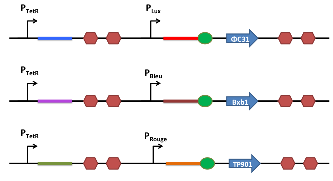
How does it work ?
This is the basic system: Two inductible promoters each followed by a RNA sequence
The blue and the red regions code for little RNA sequences.
When the promoter P2 is activated but not P1, the red sequence will be transcribed. This red sequence is partly similar to the rbs sequence (in red). When transcribed, the red sequence will block the rbs by promoting a secondary RNA structure and prevent the recombinase from being translated.

When both promoters are activated, both sequences (the blue and the red one) are transcribed. The blue RNA sequence possesses also homology with the red one. But the sequence that can anneal is longer stronger and is therefore more stable than the self annealing of the red sequence. When transcribed, the blue and the red sequences will match together and release the rbs, allowing efficient translation of the recombinase.

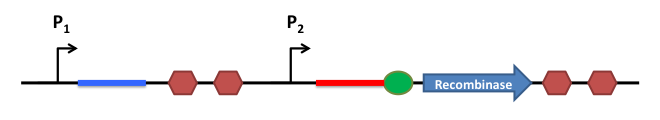
Our strategy
These publications "Genetic switchboard for synthetic biology applications" and "Engineered riboregulators enable post-transcriptional control of gene expression"inspired us. We choose to design different riboswitches keeping some sequences from the original one and changing some nucleotides. This would allow to have one specific riboregulation system for each input, avoiding potential conflicts between riboregulators.
Deeper in the design: RNA secondary structures formation
Here are presented secondary structures of two riboregulators, R0 and R1. The RBS blocking seqence anneals with a strong hairspin to the RBS. The interfering RNA has a free-end sequence complementary to an unlocking sequence of the RBS blocking RNA. When they are both transcribed, the interaction between the two RNAs let free the RBS sequence and the translation is restored.
R0 riboregulator
R0 RBS blocking RNA
The free energy of the thermodynamic ensemble is -10.14 kcal/mol.
R0 interfering RNA
The free energy of the thermodynamic ensemble is -23.27 kcal/mol.


R1 riboregulator
R1 RBS blocking RNA
The free energy of the thermodynamic ensemble is -8.72 kcal/mol.
R1 interfering RNA
The free energy of the thermodynamic ensemble is -24.10 kcal/mol.


Simulation done on RNAfold Webserver.
References:
Gruber AR, Lorenz R, Bernhart SH, Neuböck R, Hofacker IL.
The Vienna RNA Websuite. Nucleic Acids Res. 2008.
RNA parameters are described in:
Mathews DH, Disney MD, Childs JL, Schroeder SJ, Zuker M, Turner DH. (2004) Incorporating chemical modification constraints into a dynamic programming algorithm for prediction of RNA secondary structure. Proc Natl Acad Sci U S A 101(19):7287-92.

