"
"
Team:Tokyo Tech/Modeling/Crosstalk Circumvention
From 2013.igem.org

Crosstalk Circumvention Modeling
Contents |
1. Introduction
In order to achieve Signal-dependent state change circuit with crosstalk circumvention, we designed "Ninja circuit" (Fig. 4-1-1).
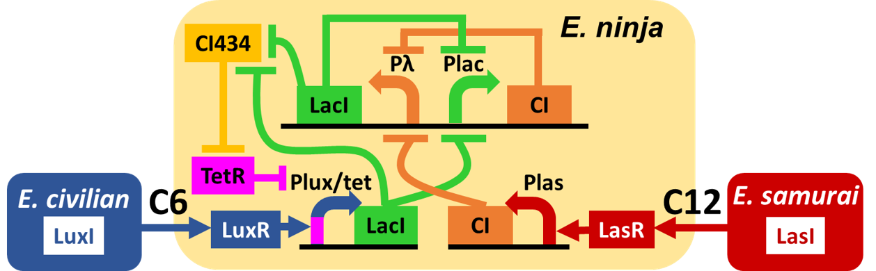
 Fig. 4-1-1. Our designed "Ninja circuit"

We analyzed the dynamic characteristics of the whole circuit through the modeling of "Ninja circuit". In addition, we verified how each parameter in the model formula affects the behavior of the circuit.
To understand the difference between our Ninja crosstalk circumvention system and the original circuit, we compared two gene circuits on equal terms.
2. Analytical method of dynamic characteristics
of the circuit
2-1. Building a mathematical model
On the basis of the Hill equation, we built a mathematical model of the "Ninja circuit". The mathematical model is shown in below. Values for each parameter are discussed on Chapter 2-3.
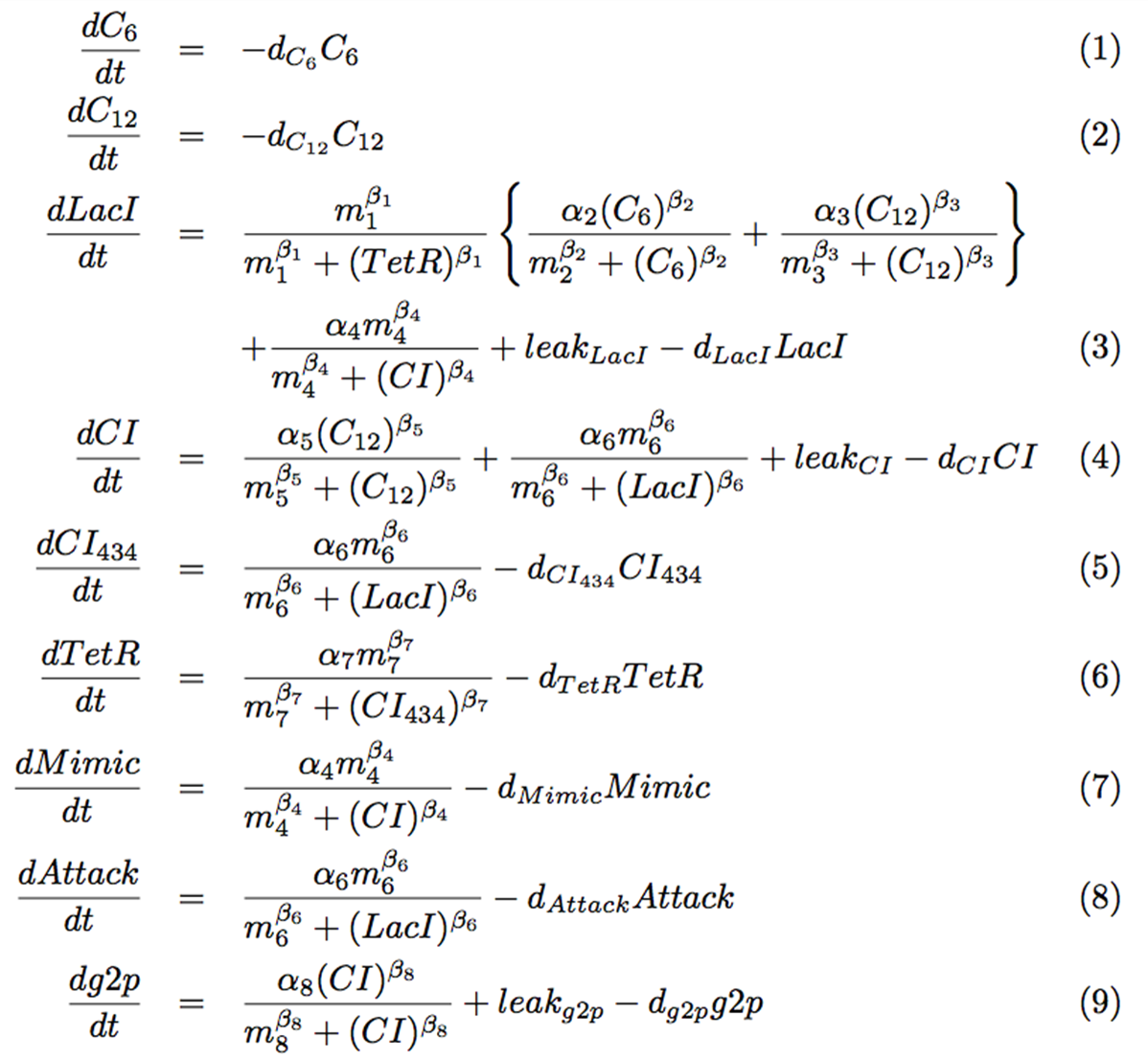 Fig. 4-1-2. Equations for our modeling

We are going to divide these equations into several groups to explain the mathematical model. The first group describes changes of the signaling molecules (Fig. 4-1-3). At this time, because of constant expression of LasR and LuxR, we considered only degradations of 3OC6HSL and 3OC12HSL. They are added as inputs in a pulse manner in this section.
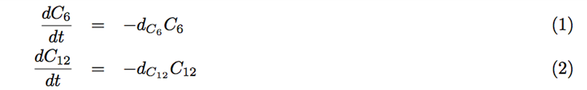 Fig. 4-1-3. Equations of degradations

Secondly, Fig. 4-1-4 shows differential equation of LacI. Since we used tet promoter (Which is repressed by TetR), the first term shows the suppression of TetR. Although hybrid promoters express LacI as an activation by 3OC6HSL, we had to consider the influence of the crosstalk, which is represented as addition. Because our result from wet experiments shows that the expression level by 3OC12HSL input, which causes crosstalk via LasR activation, is about half of that by 3OC6HSL input, we set a3 value as half of a2 value. About equation (3), not only from the hybrid promoter, LacI is also expressed from one side of the toggle switch. For this expression, we added a Hill equation to show suppression by CI. In the end, we added expression amount of the leak, then minus the decomposition item of LacI.
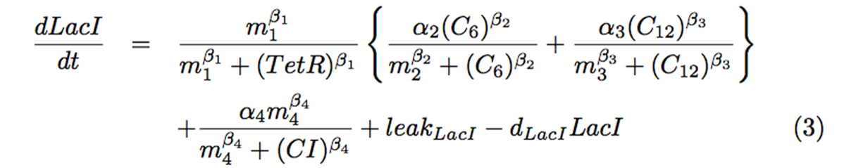 Fig. 4-1-4. The equation of LacI

As the third, CI was expressed not only from las promoter, but also from one side of the toggle switch. As a result, we added a Hill equation (Fig. 4-1-5) to show the suppression by LacI.
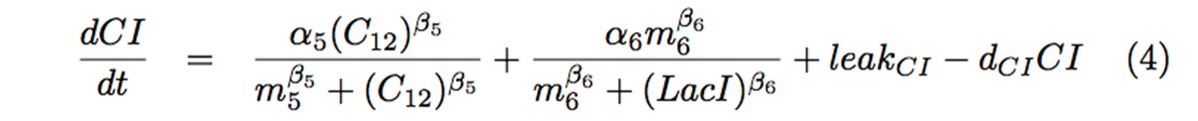 Fig. 4-1-5. The equation of CI

Finally, we derived those following equations (Fig. 4-1-6) based on the circuit as well. Mimic indicates the strength of the Mimic state, and Attack indicates the strength of the Attack state.
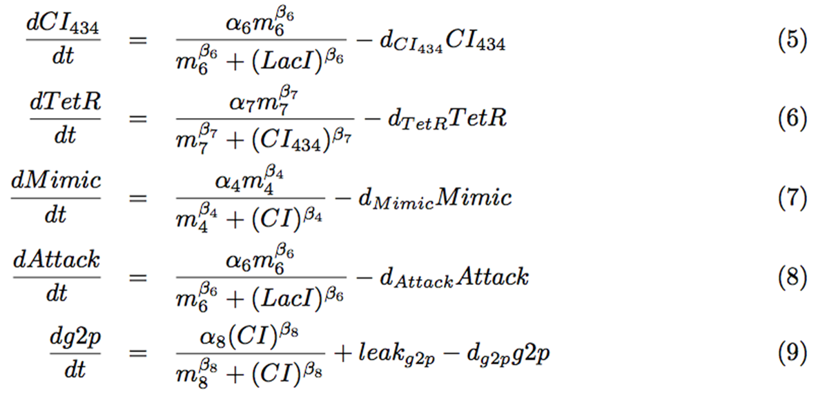 Fig. 4-1-6. Equations of CI434, TetR, Mimic, Attack, and g2p

2-2. Descriptions of the parameters
Each parameter is defined as the following table (Fig. 4-1-7).
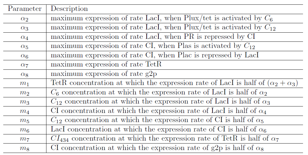 Fig. 4-1-7. Descriptions of each parameter

2-3. Parameter optimization and simulation
We carried out the simulation of this time by using MatLab. Since the amount of the parameters of the differential equation was very large, we tried to minimize the amount of the evaluation function (Fig. 4-1-8).
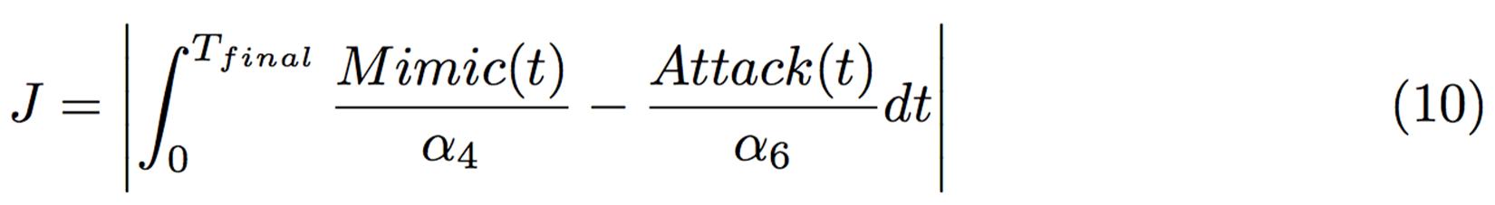 Fig. 4-1-8. The evaluation function

At time point 0, we added 3OC12HSL. Then 3OC6HSL was added at 300 min. after induction of the Mimic state in toggle switch. If the absolute value of the difference between the integral value of the strength of Attack and Mimic become smaller, we could get the conclusion that toggle switch had high performance. The parameters we explored were a4, a5, and a6. a4 and a5 are maximum expression amounts of LacI and CI in bistable state. a6 and a7 are expression amounts of CI434 and TetR as for crosstalk circumvention. We determined the transfer function of 3OC6HSL-LuxR complex by least squares method fitting from our assay result of Activation of the crosstalk circumvention system circuit by screening the concentration of 3OC6HSL and aTc, which is shown in below (Fig. 4-1-9).
 Fig. 4-1-9. Activation of our crosstalk circumvention system circuit |
 Fig. 4-1-10. Values used for fitting and the value of transfer function we determined |
We used values of GFP fluorescence intensity transition of screening the concentration of 3OC6HSL for the fitting. Since the influence lux/tet hybrid promoter gets from TetR is lower when the concentration of aTc is higher, we used values in the case of aTc = 5 µg/mL. Each values of C6 concentration and GFP fluorescence intensity is shown in Fig. 4-1-10. The value "m", the transfer function of 3OC6HSL-LuxR complex, was determined as 2 by the fitting. We used this value as m2 in our model.
As a result of fitting m2 and exploring the a4, a5, a6, and a7 to minimize the evaluation function (10), we found out that it would be the best selection if we take the parameters as follows (Fig. 4-1-11).
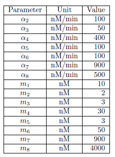 Fig. 4-1-11. Value of each parameter

2-4. Simulation results and parametric evaluation
Bistability by the toggle switch in "Ninja circuit"
We firstly confirmed bistability by toggle switch. In initial state, by pulse addition of 2 nM 3OC12HSL, the CI side got induced and maintained even after decay of 3OC12HSL. After 300 min, with pulse addition of 2 nM 3OC6HSL, the toggle switch starts switching to the Mimic state. In addition, the state was maintained after decay of 3OC12HSL. Thus we could get the conclusion that the Mimic state stays stable after the switching.
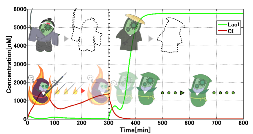 Fig. 4-1-12. Switching from CI to LacI

Then, we confirmed the performance of the other side of the toggle switch. First, 2 nM 3OC6HSL was added in a pulse manner, then after 300 min. 3OC12HSL was added in a pulse manner. From following graph (Fig. 4-1-13). in combination with Fig. 4-1-12, we could get the conclusion that the toggle switch shows bistability as we thought.
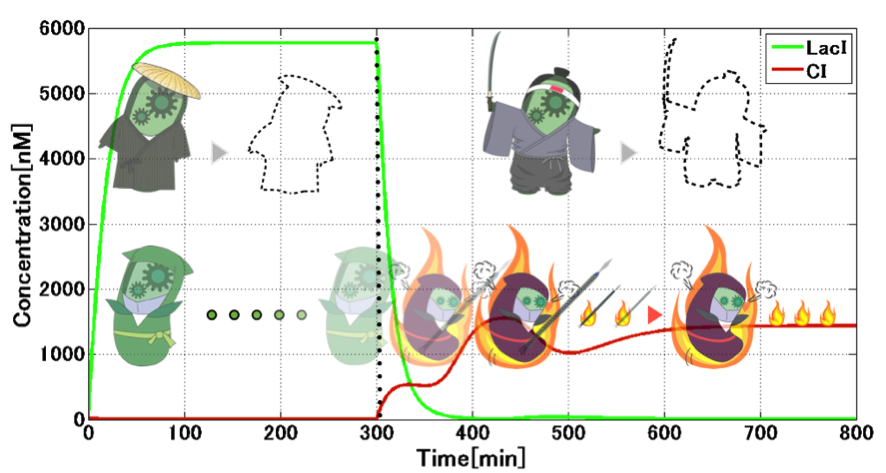 Fig. 4-1-13. Switching from LacI to CI

Crosstalk circumvention by TetR
After we confirmed the bistability by the toggle switch, we analyzed the switching dynamics.
From the following analysis, we modified equations (1) and (2) to describe presence of either E. samurai or E. civilian. Each of them accumulates a signaling molecule during its presence.
Firstly, we considered the situation that when E. ninja switches to the Mimic state. Fig. 4-1-14 shows the switching from the Attack state to the Mimic state which is influenced by 3OC6HSL getting from E. civilian. We can see from this simulation result that when E. civilian comes on the time of 300 min, the Attack state will switch to the Mimic state.
 Fig. 4-1-14. E. civilian coming (With TetR)

During the switching from the Attack state to the Mimic state, the absence of TetR allows activation of lux/tet hybrid promoter. Repression of TetR production by CI434 is indeed important in the circuit. During the Mimic state, TetR accumulates to plateau level. This presence of TetR is important to circumvent crosstalk, which is shown in the next figure (Fig. 4-1-15).
Secondly, we considered the situation that when E. ninja switches to the Attack state. When switching occurs from the Mimic state to the Attack state, CI starts its expression (Fig. 4-1-16). Note that LacI expression from the lux/tet hybrid promoter is prohibited, due to the presence of TetR, even in the presence of 3OC12HSL-LasR complex which can bind to the hybrid promoter for its activation. Abundant presence of 3OC12HSL expressed from E. samurai causes CI overexpression, which stimulates expression of g2p required for the programmed phage release. Though degradation of TetR during the presence E. samurai causes LacI expression from the hybrid promoter, CI expression from las promoter overcomes the effect of LacI. After 3OC12HSL degradation, the model shows the decrease in CI concentration, which stops throwing "shuriken" in our scenario.
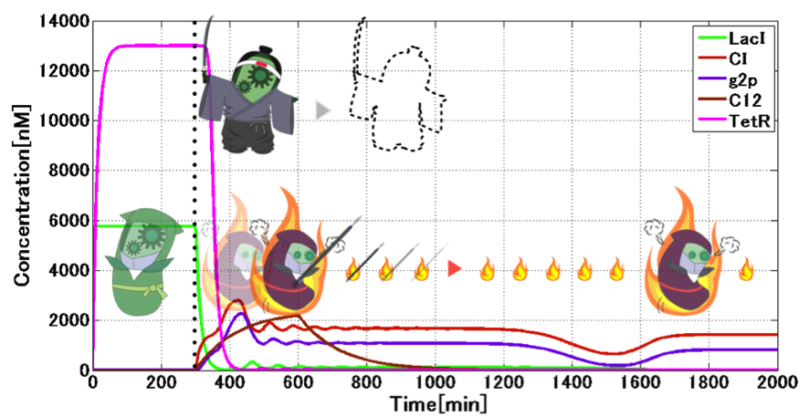 Fig. 4-1-15. E. samurai coming (With TetR)

Interestingly, CI expression oscillates and converges by 3OC12HSL induction (see time point 400-1000) (Fig. 4-1-15, which is a magnified graph of Fig. 4-1-14). This is because there is not only the toggle switch, but also a repressilator by combination among TetR, LacI and CI434. As adding 3OC12HSL from outside, TetR oscillates and decays. According to the effect, CI also vibrates and settles down to a constant value. Moreover, the amount of CI decides the expression level of g2p, so we can see g2p vibration, too.
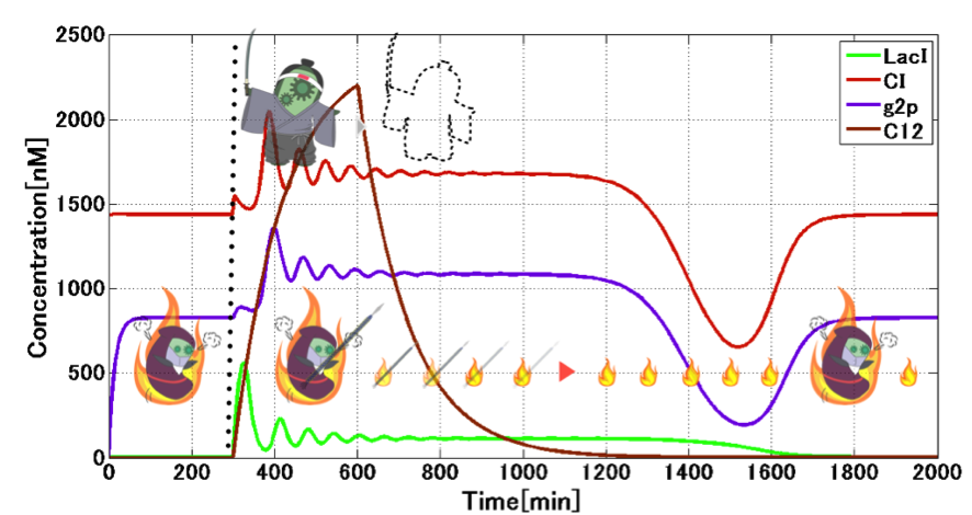 Fig. 4-1-16. Switching from the Mimic state to the Attack state

3. Analytical method of effectiveness
of crosstalk prevention circuit
3-1. Modeling without crosstalk prevention circuit
Since we already have the simulation result, to verify the difference between "Ninja circuit" and the naive "Signal-dependent state change circuit" which doesn’t circumvent the crosstalk of signal, we established the model for the naive circuit. Equations of naive circuit was defined as follows (Fig. 4-1-17).
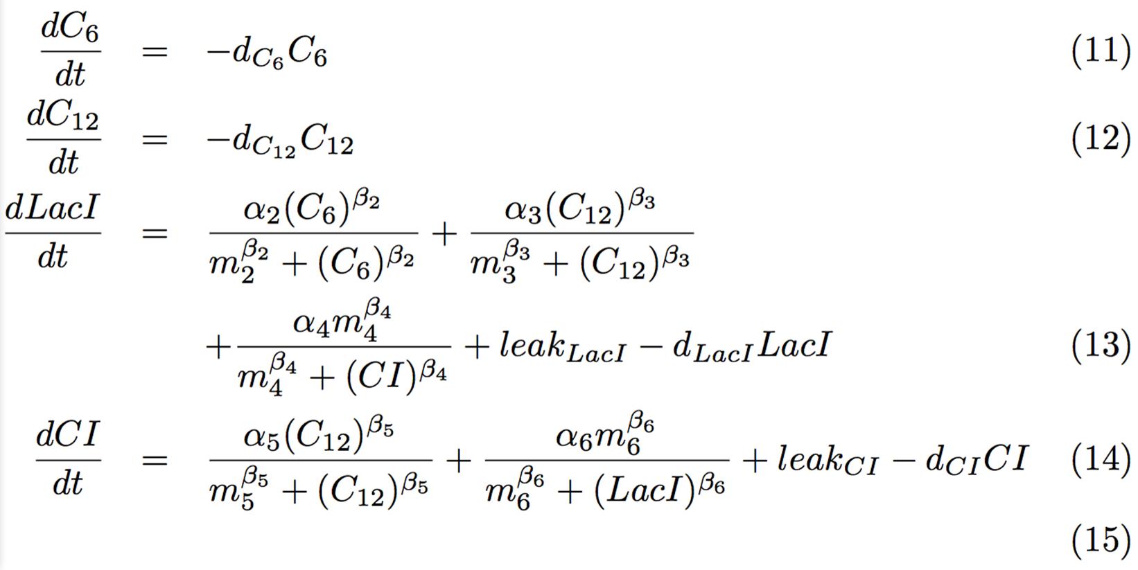 Fig. 4-1-17. Equations of naive circuit

The value of the parameters used here was the same as that used in Fig. 4-1-11.
3-2. Simulation results
For the dynamics of changing from the Mimic state to the Attack state, we compared the characteristics of both the circuit. The reason why we won’t compare characteristics for the opposite changing from CI state to LacI state is that crosstalk won’t be occur in this changing. We analyzed the following case; the initial state with enough LacI changes to the state with enough CI, by the increase of 3OC12HSL expression from E. samurai who came at 300 min. Fig. 4-1-18 shows the changing of LacI and CI. The solid line presents the case with crosstalk circumvention circuit, and the dotted line stands for the case without crosstalk circumvention circuit. With 3OC12HSL production, LacI is produced in a certain amount in the naive circuit without crosstalk circumvention. On the contrary, "Ninja circuit" actually circumvents the crosstalk to reduce LacI concentration severely. When E. samurai has gone at 1500 min. the concentration of LacI expressed by "Ninja circuit" was about 25 nM. In contrast, the concentration of LacI expressed by the naive circuit, which cannot circumvent from the crosstalk, is 725 nM. Regarding the convergence to 5 nM LacI, we can conclude that "Ninja circuit" will be converged faster than "Naive circuit".
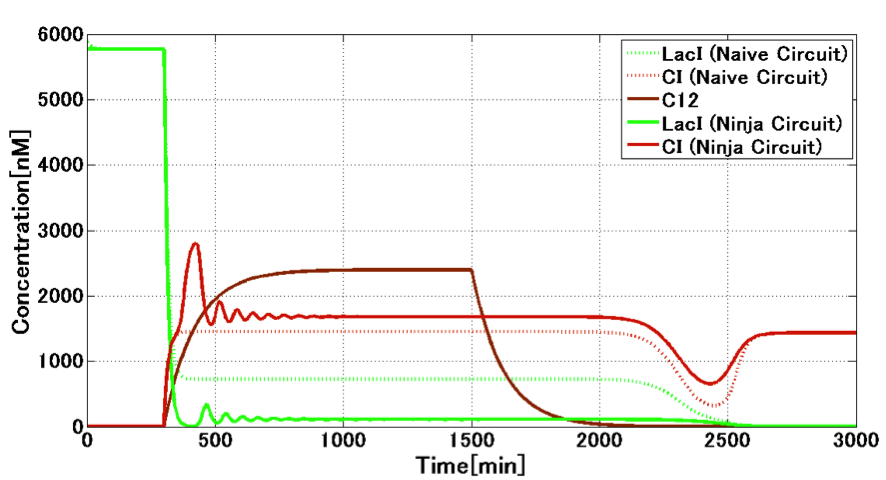 Fig. 4-1-18. Difference between "Naive circuit" and "Ninja circuit"

4. Comparing models of the circuit using ODEs and stochastic simulation
We also modeled our Ninja circuit by using stochastic simulation and examined that the circuit really should maintain its bistability on both models.
First we examined the case the Attack state switches to the Mimic state. In initial state we added 2 nM 3OC12HSL by pulse, and after 300 min we added 2 nM 3OC6HSL by pulse. The results are shown in below (Fig. 4-1-19: ODEs, Fig. 4-1-20: stochastic simulation ). Even there is an oscillation in the stochastic simulation model, we can indicate that the circuit switched from the Attack state to the Mimic state and maintained both state after decay of signals in both models.
 Fig. 4-1-19. A model using stochastic simulation of state switching from the Attack state to the Mimic state |
 Fig. 4-1-20. A model using ODEs of state switching from the Attack state to the Mimic state |
Next we examined the case the Mimic state switches to the Attack state. In initial state we added 2 nM 3OC6HSL by pulse, and after 300 min we added 2 nM 3OC12HSL by pulse. The results are shown in below (Fig. 4-1-21: ODEs, Fig. 4-1-22: stochastic simulation ). In both models, we can indicate that the circuit switched from the Mimic state to the Attack state and maintained both state after decay of signals.
 Fig. 4-1-21. A model using stochastic simulation of state switching from the Mimic state to the Attack state |
 Fig. 4-1-22. A model using ODEs of state switching from the Mimic state to the Attack state |
By these modeling results, we can say that the toggle switch shows bistability with more persuasiveness.