Team:Exeter/Project
From 2013.igem.org
(→The Biology) |
(Reverting bootstrap theme) |
||
| (59 intermediate revisions not shown) | |||
| Line 12: | Line 12: | ||
|} | |} | ||
| - | == | + | == Project Description == |
| + | Our project aims to produce a group of BioBricks organised into three modules; one each for Red, Green and Blue ([http://en.wikipedia.org/wiki/Additive_color RGB]) light. To demonstrate the system we will control the production of Cyan, Magenta and Yellow pigments, but we will also be inputting a system where future teams could have any gene as their "output" gene. We are using the CMY pigments, but you could potentially use the RGB light to control the transcription of anything. | ||
| - | + | The ultimate aim of our project is to use ([http://en.wikipedia.org/wiki/Subtractive_color CMY]) pigments to produce the world's first colour bio-photograph or | |
| - | + | ||
| - | ([http://en.wikipedia.org/wiki/Subtractive_color CMY]) pigments to produce the world's first colour bio-photograph or | + | |
[http://parts.igem.org/Coliroid coliroid]. | [http://parts.igem.org/Coliroid coliroid]. | ||
We will be building upon the work done by previous iGEM teams, most notably Texas/Austin 2004, Edinburgh 2010 and Uppsala 2011. | We will be building upon the work done by previous iGEM teams, most notably Texas/Austin 2004, Edinburgh 2010 and Uppsala 2011. | ||
| + | |||
| + | If you would like to see any of our initial brainstorming - please feel free to follow this link ([https://2013.igem.org/Team:Exeter/Brainstorming Brainstorming]) | ||
== The Camera == | == The Camera == | ||
| - | Bio-Photography is the application of genetically engineered bacteria as the light sensor of a camera, replacing digital sensors ([https://en.wikipedia.org/wiki/Image_sensor#Sensors_used_in_digital_cameras CCD/CMOS]) or photographic film. The surface area of bacteria is on the order of microns, much smaller than a digital sensor | + | Bio-Photography is the application of genetically engineered bacteria to act as the light sensor of a camera, replacing digital sensors ([https://en.wikipedia.org/wiki/Image_sensor#Sensors_used_in_digital_cameras CCD/CMOS]) or photographic film. The surface area of bacteria is on the order of microns, much smaller than a digital sensor, giving bio-cameras the potential to produce images with far greater resolution than current digital photography offers. |
We aim to produce the world's first colour bio-photograph by producing Cyan, Magenta and Yellow pigments in response to Red, Green and Blue light. We plan to combine this system with a lens to focus the image onto plated bacteria to form the world's first colour bio-camera. | We aim to produce the world's first colour bio-photograph by producing Cyan, Magenta and Yellow pigments in response to Red, Green and Blue light. We plan to combine this system with a lens to focus the image onto plated bacteria to form the world's first colour bio-camera. | ||
| Line 34: | Line 35: | ||
In our system we are using two sets of primary colours. Red, Green and Blue for light and Cyan, Magenta and Yellow for pigments. This is because light and pigment mix differently; light is additive and pigment is subtractive: | In our system we are using two sets of primary colours. Red, Green and Blue for light and Cyan, Magenta and Yellow for pigments. This is because light and pigment mix differently; light is additive and pigment is subtractive: | ||
| - | + | [[Image:Colour_wheels.png|center||500px|Image: 500 pixels]] | |
| - | Light and pigment produce colour in different ways. While coloured light has a peak wavelength | + | |
| + | Light and pigment produce colour in different ways. While coloured light has a peak wavelength corresponding to its colour, coloured pigment absorbs all wavelengths that do not correspond to its colour and so reflect the corresponding coloured light: | ||
<!-- Diagram needed --> | <!-- Diagram needed --> | ||
| - | In this system | + | In this system, red light is the opposite of cyan pigment, green light is the opposite of magenta pigment, and blue light is the opposite of yellow pigment. Hence our choice of sensors and pigments. |
| - | It must be noted that while [http://en.wikipedia.org/wiki/RGB_color_model RGB] light give a full spectrum of colour and tone | + | It must be noted that while [http://en.wikipedia.org/wiki/RGB_color_model RGB] light give a full spectrum of colour and tone, CMY is a simplified version of the CYMK colour system used in printing. This was done because to engineer the pathways for [http://en.wikipedia.org/wiki/CMYK_color_model CYMK] colour system outputs is too complex (see logic gates below). However, as CMY is subtractive there will be tone as Cyan + Magenta + Yellow will approximate black. |
| + | |||
| + | [[Image:Better_Logic_gates_including_black.png|center||500px|Image: 500 pixels]] | ||
| + | |||
| + | |||
| + | This shows the logic gates required if we included a black pigment (K). Not very simple, and near impossible to input into an <i>E. coli</i>! However, when the black pigment is removed, the logic gates simplify down very neatly... | ||
| + | |||
| + | [[Image:Better_Logic_gates_not_including_black.png|center||400px|Image: 400 pixels]] | ||
| + | |||
| + | This system shows red light suppressing the production of our cyan pigment, green light suppressing the magenta pigment and blue light supressing the yellow pigment. | ||
== The Biology == | == The Biology == | ||
| Line 50: | Line 61: | ||
In our bio-camera the controlled genes will be those that code for the production of cyan, magenta and yellow pigments: | In our bio-camera the controlled genes will be those that code for the production of cyan, magenta and yellow pigments: | ||
| - | * Red light prevents the production of | + | * Red light prevents the production of Cyan pigment |
| - | * Green light prevents the production of | + | * Green light prevents the production of Magenta pigment |
* Blue light prevents the production of Yellow pigment | * Blue light prevents the production of Yellow pigment | ||
| - | + | [[Image:Light_to_Pigment_Repression.png|center||300px|Image: 300 pixels]] | |
| + | |||
Each sensor prevents the production of its opposing pigment, producing the pigment which is the same colour of light that the light sensor detects. The mix of pigments will reproduce the colour of light incident on the bacteria. | Each sensor prevents the production of its opposing pigment, producing the pigment which is the same colour of light that the light sensor detects. The mix of pigments will reproduce the colour of light incident on the bacteria. | ||
| + | |||
| + | If you'd like to have a go at mixing pigments and lights for yourself, why not play the colour mixing game at the bottom of our Notebook page? More difficult than you'd think! | ||
=== Red light pathway === | === Red light pathway === | ||
| - | This pathway uses the well characterised Cph8 red light sensor (composing of Cph1 and Envz) | + | This pathway uses the well characterised Cph8 red light sensor (composing of Cph1 and Envz). When there is no red light present, this protein causes the phosphorylation of OmpR, to OmpR-P. This then diffuses away from the red light sensor, and can bind to a specialised OmpF promoter sequence which is upstream of the HO-pcyA gene which codes for cyan pigment and stop codon. This is then transcribed and cyan pigment is produced. |
| - | + | When Cph8 is exposed to red light, the phosphorylation of OmpR ceases. The OmpR is not capable of diffusing away from the red light sensor, so does not bind to the OmpF promoter before the cyan pigment gene. This means that the cyan pigment can not be generated. Cyan pigment in this system will be repressed, whereas magenta and yellow pigments will still be produced, which when mixed create a red pigment. | |
| - | + | [[Image:Red_Pathway.png|center||600px|Image: 600 pixels]] | |
=== Green light pathway === | === Green light pathway === | ||
| - | The | + | The green light module works differently to the red and blue light modules but it still uses a light sensor (CcaS), intermediate protein (CcaR) and a specialised promoter. However, when the system is exposed to green light, CcaR is phosphorylated and CcaR-P is generated, allowing the synthesis of the magenta pigment to be up regulated instead of prevented. To make an overall green colour, we only want the yellow and cyan pigments to be transcribed, so production of the magenta pigment is problematic. |
| + | |||
| + | To overcome this issue, we will introduce an inverter system. CcaR-P will be produced when the bacteria are exposed to green light, but instead of binding to a promoter placed before the gene coding for magenta pigment, it will bind to a cI repressor system. The subsequent transcription of the cI repressor protein will prevent the synthesis of the magenta pigment, as it will bind to a cI promoter. Binding of cI to this promoter ceases transcription of any following genes, therefore magenta will not be produced. | ||
| + | |||
| + | [[Image:Green_Pathway.png|center||600px|Image: 600 pixels]] | ||
=== Blue light pathway === | === Blue light pathway === | ||
| - | + | The YtvA/FixL blue light sensor phosphorylates FixJ to FixJ-p in the absence of blue light. FixJ-p then binds to the promoter for the yellow pigment gene and stop codon. In the absence of blue light the Yellow pigment is produced. | |
| - | + | The blue light module works in much the same way as the red light module; absence of blue light allows the phosphorylation of an intermediate protein (FixJ) by the blue light sensor (YF1). FixJ can then bind to its specialised promoter which controls the transcription of the yellow pigment (amilGFP). Exposure to blue light leads to the suppression in production of the yellow pigment. | |
| - | |||
| - | + | The remaining pigments, magenta and cyan, will combine to form a blue colour. | |
| - | + | [[Image:Blue_Pathway.png|center||600px|Image: 600 pixels]] | |
| + | <!-- Yep, put both diagrams up! How about separating them up so we have the text for the diagram where red light is not present,then the diagram of that. then the text for the diagram where red light is present, then the diagram for that one? or if that looks bizarre just put them both together after the text--> | ||
| + | |||
| + | === The Future === | ||
| + | |||
| + | Our project aims to provide a foundation for the control of organisms using multiple wavelengths of light for future development. Using lasers to control bacteria will provide high spatial control, while a well characterised system will provide good temporal control. Importantly, response is not limited to a molecular output. Possibilities include taxis, luminescence, electricity, magnetic fields and sound. As has been proven in past research, systems expressed in ''E.coli'' can be modified and expressed in a eukaryotic model. In consideration, such a system could enable finely controlled mixed volume outputs of medically relevant molecules, for example patient specific antibody treatment. From an economic angle, a calculatable light input will correlate to a desired complex output from a single customizable organism strain, vastly increasing production times from current processes. Attractively, laboratories will have reduced chemical usage and only require a single processing machine, as light is a cheap, easily manipulatable and mostly harm free resource. | ||
| + | |||
<!-- High spatial and medium temporal control over each output should also be possible by the use of multi-wavelength lasers. This has many potential applications from the manufacturing of composite materials to control of engineered organisms in an environment. | <!-- High spatial and medium temporal control over each output should also be possible by the use of multi-wavelength lasers. This has many potential applications from the manufacturing of composite materials to control of engineered organisms in an environment. | ||
| Line 90: | Line 113: | ||
For the blue and red light sensors, the presence of their corresponding wavelength of light causes autophosphorylation of an intermediate protein. Phosphorylated intermediates then freely bind as repressors to the corresponding output gene (cyan for red light, yellow for blue light). With the green light sensor, a signal inverter will be introduced, as the FixJ system acts as an activator not a repressor (the exact opposite of what we want). Instead of acting on the gene coding for the output (magenta) the phosphorylated intermediate binds instead to a gene coding for the cI protein used in the lambda phage (a bacteriophage which infects E. coli). Once synthesised the cl protein acts as the output (magenta) repressor. --> | For the blue and red light sensors, the presence of their corresponding wavelength of light causes autophosphorylation of an intermediate protein. Phosphorylated intermediates then freely bind as repressors to the corresponding output gene (cyan for red light, yellow for blue light). With the green light sensor, a signal inverter will be introduced, as the FixJ system acts as an activator not a repressor (the exact opposite of what we want). Instead of acting on the gene coding for the output (magenta) the phosphorylated intermediate binds instead to a gene coding for the cI protein used in the lambda phage (a bacteriophage which infects E. coli). Once synthesised the cl protein acts as the output (magenta) repressor. --> | ||
| + | |||
| + | <!--•Light receptors and pathways well characterised | ||
| + | •Finely controlled output through variable light input | ||
| + | •Ultra high resolution bio-camera (gigapixel) - physicists may have to explain this one!! | ||
| + | •Complex materials manufacturing (silk??) | ||
| + | •Cheap, simple and effective way of testing systems in the laboratory | ||
| + | These ideas are from the london presentation)--> | ||
| + | |||
| + | == So what do our constructs look like? == | ||
| + | |||
| + | As we have the three different light modules to work with, we can experiment with different techniques and companies when it comes to our assembly techniques and synthesis. | ||
| + | |||
| + | [[Image:Better_Diagram_of_Red_Plasmid.png|center||600px|Image: 600 pixels]] | ||
| + | |||
| + | The Red Light Module is the "easiest" to work with, as we only need to be working with the red light sensor and cyan pigment (the intermediate protein, OmpR, is already present in the genome of <i>E. coli</i>, so we don't need to include the genes which code for it). We will try and assemble this module ourselves in the lab, using a variety of assembly techniques. | ||
| + | |||
| + | The pink arrows indicate the direction of transcription. OmpF is the specific promoter which matches OmpR, the intermediate protein. The black brackets indicate the separate BioBricks (eg. BBa_S05058 is an RBS with the gene that codes for our cyan pigment). | ||
| + | |||
| + | The cyan pigment has been placed before the red light sensor so that if there is accidental read-through, we're not getting unwanted transcription of the cyan pigment. | ||
| + | |||
| + | [[Image:Better_Diagram_of_Blue_plasmid.png|center||700px|Image: 700 pixels]] | ||
| + | |||
| + | The Blue Light Module is being synthesised for us by DNA2.0. It includes YFI (our blue light sensor), FixJ (the intermediate protein) and amilGFP (our yellow pigment). | ||
| + | |||
| + | The pink arrows indicate the direction of transcription. The central section, coding for FixJ, has been flipped backwards and upside-down. This ensure that, if we get accidental read-through from the RNA polymerase from YF1, the sequence for FixJ will code for nonsense. Nothing will be made which will interfere with our system. | ||
| + | |||
| + | Again, the black brackets indicate individual BioBricks. The "TACTAG" indicates a sequence of TACTAG "scars" to space out the promoter for FixJ and the promoter for the yellow pigment. This is more of a precaution than anything else. The list of "STOP" codons acts a terminator. | ||
| + | |||
| + | [[Image:Better_Diagram_of_Green_plasmid.png|center||800px|Image: 800 pixels]] | ||
| + | |||
| + | The Green Light Module is being synthesised using IDT gBlocks. cR indicates the promoter where the cI inverter protein binds. Again, we have some TACTAG spacers between the promoters, and some sections have been flipped backwards and upside-down. The directions of transcription are shown with pink arrows. | ||
Latest revision as of 14:01, 22 August 2013
| Home | Team | Official Team Profile | Project | Part Submissions | Modelling | Notebook | Safety | Attributions |
|---|
Contents |
Project Description
Our project aims to produce a group of BioBricks organised into three modules; one each for Red, Green and Blue ([http://en.wikipedia.org/wiki/Additive_color RGB]) light. To demonstrate the system we will control the production of Cyan, Magenta and Yellow pigments, but we will also be inputting a system where future teams could have any gene as their "output" gene. We are using the CMY pigments, but you could potentially use the RGB light to control the transcription of anything.
The ultimate aim of our project is to use ([http://en.wikipedia.org/wiki/Subtractive_color CMY]) pigments to produce the world's first colour bio-photograph or [http://parts.igem.org/Coliroid coliroid].
We will be building upon the work done by previous iGEM teams, most notably Texas/Austin 2004, Edinburgh 2010 and Uppsala 2011.
If you would like to see any of our initial brainstorming - please feel free to follow this link (Brainstorming)
The Camera
Bio-Photography is the application of genetically engineered bacteria to act as the light sensor of a camera, replacing digital sensors (CCD/CMOS) or photographic film. The surface area of bacteria is on the order of microns, much smaller than a digital sensor, giving bio-cameras the potential to produce images with far greater resolution than current digital photography offers.
We aim to produce the world's first colour bio-photograph by producing Cyan, Magenta and Yellow pigments in response to Red, Green and Blue light. We plan to combine this system with a lens to focus the image onto plated bacteria to form the world's first colour bio-camera.
Colour system
To produce the full colour spectrum requires all three [http://en.wikipedia.org/wiki/Primary_color primary colours]. This is because any colour can be produced by mixing the primary colours but primary colours cannot be produced by mixing any colours.
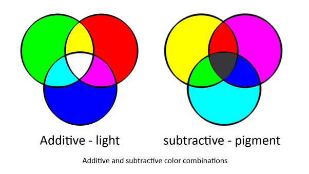
In our system we are using two sets of primary colours. Red, Green and Blue for light and Cyan, Magenta and Yellow for pigments. This is because light and pigment mix differently; light is additive and pigment is subtractive:
Light and pigment produce colour in different ways. While coloured light has a peak wavelength corresponding to its colour, coloured pigment absorbs all wavelengths that do not correspond to its colour and so reflect the corresponding coloured light:
In this system, red light is the opposite of cyan pigment, green light is the opposite of magenta pigment, and blue light is the opposite of yellow pigment. Hence our choice of sensors and pigments.
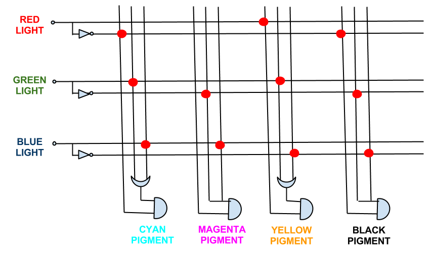
It must be noted that while [http://en.wikipedia.org/wiki/RGB_color_model RGB] light give a full spectrum of colour and tone, CMY is a simplified version of the CYMK colour system used in printing. This was done because to engineer the pathways for [http://en.wikipedia.org/wiki/CMYK_color_model CYMK] colour system outputs is too complex (see logic gates below). However, as CMY is subtractive there will be tone as Cyan + Magenta + Yellow will approximate black.
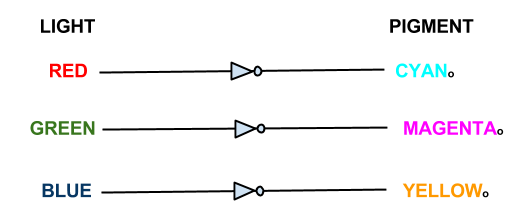
This shows the logic gates required if we included a black pigment (K). Not very simple, and near impossible to input into an E. coli! However, when the black pigment is removed, the logic gates simplify down very neatly...
This system shows red light suppressing the production of our cyan pigment, green light suppressing the magenta pigment and blue light supressing the yellow pigment.
The Biology
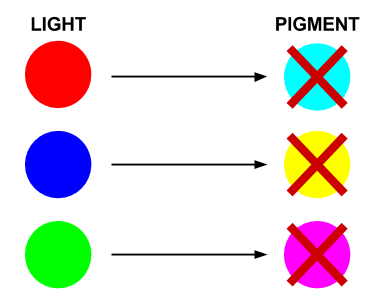
The focus of our wet work is the creation of three independent 'light to output' pathways in E. coli. Each pathway will control the transcription of selected genes using Red, Green or Blue light. Incident light will prevent the transcription of the selected gene.
In our bio-camera the controlled genes will be those that code for the production of cyan, magenta and yellow pigments:
- Red light prevents the production of Cyan pigment
- Green light prevents the production of Magenta pigment
- Blue light prevents the production of Yellow pigment
Each sensor prevents the production of its opposing pigment, producing the pigment which is the same colour of light that the light sensor detects. The mix of pigments will reproduce the colour of light incident on the bacteria.
If you'd like to have a go at mixing pigments and lights for yourself, why not play the colour mixing game at the bottom of our Notebook page? More difficult than you'd think!
Red light pathway
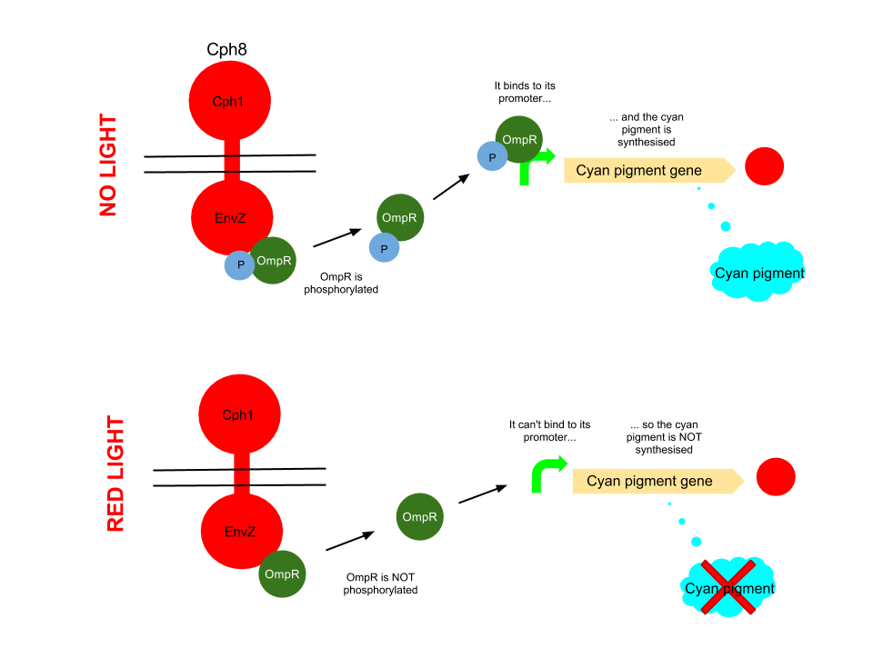
This pathway uses the well characterised Cph8 red light sensor (composing of Cph1 and Envz). When there is no red light present, this protein causes the phosphorylation of OmpR, to OmpR-P. This then diffuses away from the red light sensor, and can bind to a specialised OmpF promoter sequence which is upstream of the HO-pcyA gene which codes for cyan pigment and stop codon. This is then transcribed and cyan pigment is produced.
When Cph8 is exposed to red light, the phosphorylation of OmpR ceases. The OmpR is not capable of diffusing away from the red light sensor, so does not bind to the OmpF promoter before the cyan pigment gene. This means that the cyan pigment can not be generated. Cyan pigment in this system will be repressed, whereas magenta and yellow pigments will still be produced, which when mixed create a red pigment.
Green light pathway
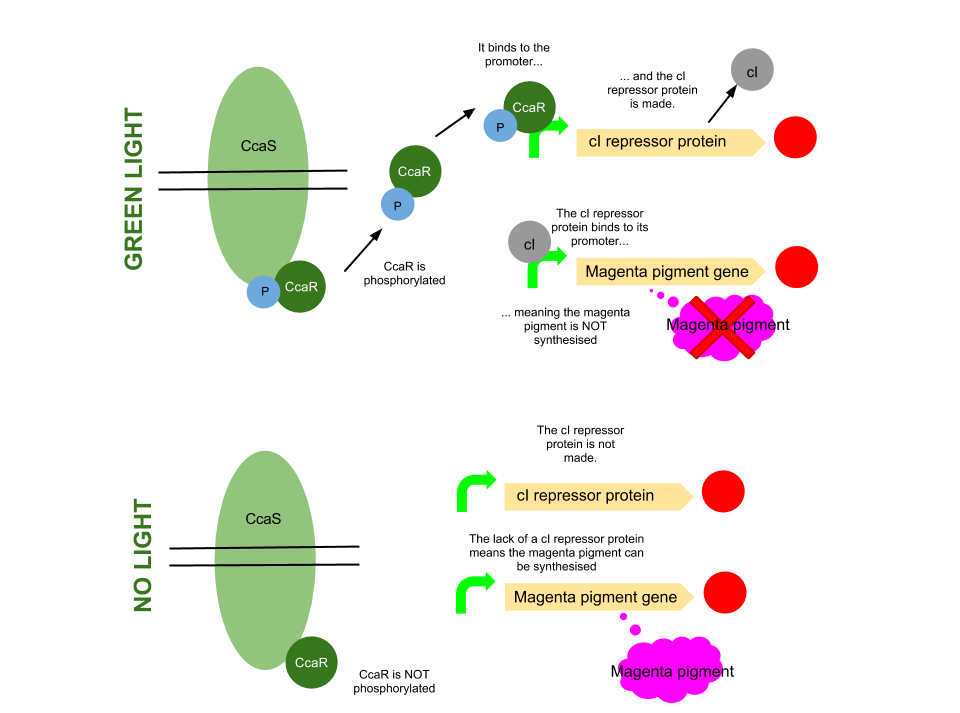
The green light module works differently to the red and blue light modules but it still uses a light sensor (CcaS), intermediate protein (CcaR) and a specialised promoter. However, when the system is exposed to green light, CcaR is phosphorylated and CcaR-P is generated, allowing the synthesis of the magenta pigment to be up regulated instead of prevented. To make an overall green colour, we only want the yellow and cyan pigments to be transcribed, so production of the magenta pigment is problematic.
To overcome this issue, we will introduce an inverter system. CcaR-P will be produced when the bacteria are exposed to green light, but instead of binding to a promoter placed before the gene coding for magenta pigment, it will bind to a cI repressor system. The subsequent transcription of the cI repressor protein will prevent the synthesis of the magenta pigment, as it will bind to a cI promoter. Binding of cI to this promoter ceases transcription of any following genes, therefore magenta will not be produced.
Blue light pathway
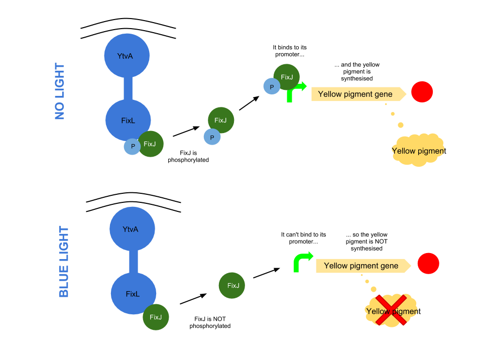
The YtvA/FixL blue light sensor phosphorylates FixJ to FixJ-p in the absence of blue light. FixJ-p then binds to the promoter for the yellow pigment gene and stop codon. In the absence of blue light the Yellow pigment is produced.
The blue light module works in much the same way as the red light module; absence of blue light allows the phosphorylation of an intermediate protein (FixJ) by the blue light sensor (YF1). FixJ can then bind to its specialised promoter which controls the transcription of the yellow pigment (amilGFP). Exposure to blue light leads to the suppression in production of the yellow pigment.
The remaining pigments, magenta and cyan, will combine to form a blue colour.
The Future
Our project aims to provide a foundation for the control of organisms using multiple wavelengths of light for future development. Using lasers to control bacteria will provide high spatial control, while a well characterised system will provide good temporal control. Importantly, response is not limited to a molecular output. Possibilities include taxis, luminescence, electricity, magnetic fields and sound. As has been proven in past research, systems expressed in E.coli can be modified and expressed in a eukaryotic model. In consideration, such a system could enable finely controlled mixed volume outputs of medically relevant molecules, for example patient specific antibody treatment. From an economic angle, a calculatable light input will correlate to a desired complex output from a single customizable organism strain, vastly increasing production times from current processes. Attractively, laboratories will have reduced chemical usage and only require a single processing machine, as light is a cheap, easily manipulatable and mostly harm free resource.
So what do our constructs look like?
As we have the three different light modules to work with, we can experiment with different techniques and companies when it comes to our assembly techniques and synthesis.
The Red Light Module is the "easiest" to work with, as we only need to be working with the red light sensor and cyan pigment (the intermediate protein, OmpR, is already present in the genome of E. coli, so we don't need to include the genes which code for it). We will try and assemble this module ourselves in the lab, using a variety of assembly techniques.
The pink arrows indicate the direction of transcription. OmpF is the specific promoter which matches OmpR, the intermediate protein. The black brackets indicate the separate BioBricks (eg. BBa_S05058 is an RBS with the gene that codes for our cyan pigment).
The cyan pigment has been placed before the red light sensor so that if there is accidental read-through, we're not getting unwanted transcription of the cyan pigment.
The Blue Light Module is being synthesised for us by DNA2.0. It includes YFI (our blue light sensor), FixJ (the intermediate protein) and amilGFP (our yellow pigment).
The pink arrows indicate the direction of transcription. The central section, coding for FixJ, has been flipped backwards and upside-down. This ensure that, if we get accidental read-through from the RNA polymerase from YF1, the sequence for FixJ will code for nonsense. Nothing will be made which will interfere with our system.
Again, the black brackets indicate individual BioBricks. The "TACTAG" indicates a sequence of TACTAG "scars" to space out the promoter for FixJ and the promoter for the yellow pigment. This is more of a precaution than anything else. The list of "STOP" codons acts a terminator.
The Green Light Module is being synthesised using IDT gBlocks. cR indicates the promoter where the cI inverter protein binds. Again, we have some TACTAG spacers between the promoters, and some sections have been flipped backwards and upside-down. The directions of transcription are shown with pink arrows.
 "
"
