 "
"
Team:INSA Toulouse/contenu/project/binary reminder
From 2013.igem.org
| Line 29: | Line 29: | ||
.texteleft{color:#5a6060; font-family:'Open Sans'; font-size:14px; display:block; float:left; width:340px; margin:0 30px 50px 0;} | .texteleft{color:#5a6060; font-family:'Open Sans'; font-size:14px; display:block; float:left; width:340px; margin:0 30px 50px 0;} | ||
| + | |||
| + | .texteleft500{color:#5a6060; font-family:'Open Sans'; font-size:14px; display:block; float:left; width:500px; margin:0 30px 50px 0;} | ||
.texteright{color:#5a6060; font-family:'Open Sans'; font-size:14px; display:block; float:right; width:340px; margin:0 0 50px 0;} | .texteright{color:#5a6060; font-family:'Open Sans'; font-size:14px; display:block; float:right; width:340px; margin:0 0 50px 0;} | ||
| + | |||
| + | .texteright500{color:#5a6060; font-family:'Open Sans'; font-size:14px; display:block; float:right; width:500px; margin:0 0 50px 0;} | ||
| + | |||
| + | .texteright450{color:#5a6060; font-family:'Open Sans'; font-size:14px; display:block; float:right; width:450px; margin:0 0 50px 0;} | ||
.spantitle{color:#5a6060; font-family:'Open Sans'; font-weight:600; font-size:18px;} | .spantitle{color:#5a6060; font-family:'Open Sans'; font-weight:600; font-size:18px;} | ||
| Line 43: | Line 49: | ||
.imgcontent{margin: 0 0 45px 0; border: 1px solid #e5e6e6;} | .imgcontent{margin: 0 0 45px 0; border: 1px solid #e5e6e6;} | ||
| + | |||
| + | .imgcontentright{margin: 0 0 45px 0; border: 1px solid #e5e6e6;float:right;} | ||
| + | |||
| + | .imgcontentleft{margin: 0 10px 45px 0; border: 1px solid #e5e6e6;float:left;} | ||
.tablecontent{ | .tablecontent{ | ||
| Line 59: | Line 69: | ||
filter:progid:DXImageTransform.Microsoft.Shadow(color=#e5e6e6, Direction=180, Strength=0);} | filter:progid:DXImageTransform.Microsoft.Shadow(color=#e5e6e6, Direction=180, Strength=0);} | ||
| - | .tablecontent tr{height:42px; color:#5a6060; font-family:'Open Sans'; font-size:14px;} | + | .tablecontent tr{height:42px; color:#5a6060; font-family:'Open Sans'; font-size:14px;text-align:center;} |
.tablecontent td{padding:0 25px 0 20px;} | .tablecontent td{padding:0 25px 0 20px;} | ||
| Line 70: | Line 80: | ||
<div class="maincontent" style="width: 720px; margin: 25px 0 25px 0; float: right;"> | <div class="maincontent" style="width: 720px; margin: 25px 0 25px 0; float: right;"> | ||
| - | |||
| - | |||
| - | < | + | <h1 class="title1">Boolean Logic Based Devices</h1> |
| - | + | ||
| + | |||
| + | <h2 class="title2">What is a logic gate?</h2> | ||
<br> | <br> | ||
| + | <p class="texte">A logic gate is an idealized or physical device implementing a Boolean function. In other terms it performs a logical operation on one or more logical inputs and produces a single logical output <a href="http://en.wikipedia.org/wiki/Logic_gate" target="_blank">(From Wikipedia)</a>. Simply said: logic gates are the devices that perform the boolean logic operations.</p> | ||
| + | <p class="texteleft"><span class="spantitle">AND Gate</span></br> | ||
| + | <br>For an AND gate, if the two inputs are equal to 1, the result equals 1.<p> | ||
| + | |||
| + | <img src="https://static.igem.org/mediawiki/2013/2/2a/AND_Gate_-_30%2C5%25.png" class="imgcontentleft" /> | ||
| + | |||
| + | <img src="https://static.igem.org/mediawiki/2013/7/75/AND_Truthtable_-_30%2C5%25.png" class="imgcontentright" /> | ||
| + | |||
| + | |||
| + | <div class="clear"></div> | ||
<br> | <br> | ||
| - | |||
| - | |||
| - | |||
| - | |||
| - | |||
| - | |||
| + | <p class="texteleft"><span class="spantitle">OR Gate</span></br> | ||
| + | <br>For an OR gate, if one or the other (or both) of the inputs are equal to 1, the result equals 1.<p> | ||
| + | <img src="https://static.igem.org/mediawiki/2013/2/2e/OR_Gate_-_30%2C5%25.png" class="imgcontentleft" /> | ||
| - | + | <img src="https://static.igem.org/mediawiki/2013/8/8d/OR_Truthtable_-_30%2C5%25.png" class="imgcontentright" /> | |
| - | + | <div class="clear"></div> | |
| - | + | ||
| - | + | ||
| - | + | ||
| - | + | ||
| - | + | ||
| - | + | ||
| - | + | ||
<br> | <br> | ||
| - | |||
| - | |||
| + | <p class="texteleft"><span class="spantitle">XOR Gate</span></br> | ||
| + | <br>For a XOR gate, if one or the other (but not both of them) of the inputs are equal to 1, the result equals 1.<p> | ||
| + | <img src="https://static.igem.org/mediawiki/2013/7/77/XOR_Gate_-_30%2C5%25.png" class="imgcontentleft" /> | ||
| + | <img src="https://static.igem.org/mediawiki/2013/7/71/XOR_Truthtable_-_30%2C5%25.png" class="imgcontentright" /> | ||
| + | |||
| + | <div class="clear"></div> | ||
<br> | <br> | ||
| - | |||
| - | |||
| + | |||
| + | |||
| + | <p class="texte"><span class="spantitle">Electronic Full Adder</span></p> | ||
| + | |||
| + | <img src="https://static.igem.org/mediawiki/2013/9/9b/400px-Full_Adder.png" class="imgcontent" /> | ||
| + | |||
| + | <p class="texteright450">This is the truth table of a full adder.<p> | ||
| + | |||
| + | <img src="https://static.igem.org/mediawiki/2013/5/52/Table_vérité_addition_-_200px.png" class="imgcontentleft" /> | ||
| + | |||
| + | <div class="clear"></div> | ||
| + | |||
| + | |||
| + | |||
| + | |||
| + | |||
| + | |||
| + | <h2 class="title2">How to count with binary numbers?</h2> | ||
| + | |||
| + | <p class="texte">For those who don’t remember your binary counting courses (or for those who don’t have any idea about binary counting), we provide a little reminder!</p> | ||
| - | + | <img src="https://static.igem.org/mediawiki/2013/c/c4/Binary_decimal_2.png" class="imgcontent" /> | |
| + | |||
| + | <table class="tablecontent"> | ||
| + | <tr style="background-color:#20a8da; height:50px; color:#ffffff;" > | ||
| + | <td style="border-bottom:4px solid #e5e6e6; border-top-left-radius:9px;"> </td> | ||
| + | <td style="border-bottom:4px solid #e5e6e6; " colspan = "2">Operation</td> | ||
| + | <td style="border-bottom:4px solid #e5e6e6; border-top-right-radius:9px;">Result</td> | ||
| + | </tr> | ||
| + | <tr> | ||
| + | <td style="border-right:1px solid #e5e6e6;">Decimal</td> | ||
| + | <td style="border-right:1px solid #e5e6e6;">5</td> | ||
| + | <td style="border-right:1px solid #e5e6e6;">2</td> | ||
| + | <td>7</td> | ||
| + | </tr> | ||
| + | <tr style="border-top:1px solid #e5e6e6"> | ||
| + | <td style="border-right:1px solid #e5e6e6; border-top:1px solid #e5e6e6;">Binary</td> | ||
| + | <td style="border-right:1px solid #e5e6e6; border-top:1px solid #e5e6e6;">1 (1*2^2)<br>0 (0*2^1)<br>1 (1*2^0)</td> | ||
| + | <td style="border-right:1px solid #e5e6e6; border-top:1px solid #e5e6e6;">0 (0*2^2)<br>1 (1*2^1)<br>0 (0*2^0)</td> | ||
| + | <td style="border-top:1px solid #e5e6e6;">1 (1*2^2)<br>1 (1*2^1)<br>1 (1*2^0)</td> | ||
| + | </tr> | ||
| + | </table> | ||
Revision as of 14:23, 3 October 2013
Boolean Logic Based Devices
What is a logic gate?
A logic gate is an idealized or physical device implementing a Boolean function. In other terms it performs a logical operation on one or more logical inputs and produces a single logical output (From Wikipedia). Simply said: logic gates are the devices that perform the boolean logic operations.
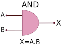
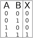
AND Gate
For an AND gate, if the two inputs are equal to 1, the result equals 1.
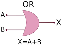
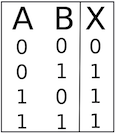
OR Gate
For an OR gate, if one or the other (or both) of the inputs are equal to 1, the result equals 1.
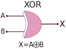
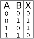
XOR Gate
For a XOR gate, if one or the other (but not both of them) of the inputs are equal to 1, the result equals 1.
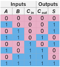
Electronic Full Adder

This is the truth table of a full adder.
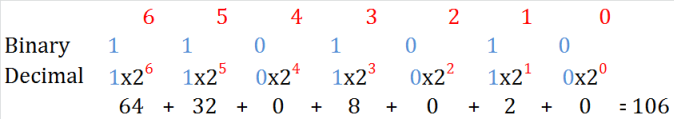
How to count with binary numbers?
For those who don’t remember your binary counting courses (or for those who don’t have any idea about binary counting), we provide a little reminder!
| Operation | Result | ||
| Decimal | 5 | 2 | 7 |
| Binary | 1 (1*2^2) 0 (0*2^1) 1 (1*2^0) |
0 (0*2^2) 1 (1*2^1) 0 (0*2^0) |
1 (1*2^2) 1 (1*2^1) 1 (1*2^0) |

