 "
"
Timer Plus Sumo
From 2013.igem.org
| Line 77: | Line 77: | ||
|Degradation rate of TET | |Degradation rate of TET | ||
|min<sup>-1</sup> | |min<sup>-1</sup> | ||
| - | | [[Team:TUDelft/Modeling_References|[ | + | | [[Team:TUDelft/Modeling_References|[9]]] |
| + | |- | ||
| + | | d<sub>CI;</sub> | ||
| + | |0.042 | ||
| + | |Degradation rate of CI | ||
| + | |min<sup>-1</sup> | ||
| + | | [[Team:TUDelft/Modeling_References|[9]]] | ||
| + | |- | ||
| + | | d<sub>PEP;</sub> | ||
| + | |6.3*10<sup>-3</sup> | ||
| + | |Degradation rate of the peptide | ||
| + | |min<sup>-1</sup> | ||
| + | |Assumption | ||
|- | |- | ||
| - | |||
|} | |} | ||
</p> | </p> | ||
Revision as of 09:08, 16 August 2013
Timer Plus Sumo
In this section the system of Figure 1 is modeled. The structure of the timer is very similar version of the timer compared to the construct of iGEM TU Delft team 2009. Here the input is changed to a T7 promoter and the output to Ulp-1. Furthermore, the Ulp-1 cleaves off the SUMO from the peptide combined with the SUMO.
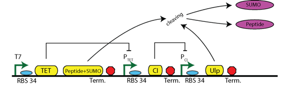
Figure 1: Circuit of the timer including sumo cleaving
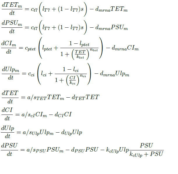
Differential Equations
The above circuit can be represented by the following differential equations. We assume a binary behavior of the T7 promoter. In the presence of IPTG, the T7 promoter will be active. So, we make the assumption that the T7 is binary variable with two possible states: either active 1 or inactive 0.
Parameters
| Parameter | Value | Description | Units | Reference |
| ca | 1020 | Translation rate per amino acid | min-1#a-1 | [7] |
| cT7 | 4.16 | Maximum transcription rate of T7 | #m/min | [2] |
| cptet; | 2.79 | Maximum transcription rate of Ptet | #m/min | [4] |
| cci; | 1.79 | Maximum transcription rate of Pci | #m/min | [3] |
| dmRNA; | 0.231 | Degradation rate of mRNA | min-1 | [8] |
| dTET; | 0.1386 | Degradation rate of TET | min-1 | [9] |
| dCI; | 0.042 | Degradation rate of CI | min-1 | [9] |
| dPEP; | 6.3*10-3 | Degradation rate of the peptide | min-1 | Assumption |
Simulation
Initial Conditions
TET and ULP must be set equal to zero (or a numerical equivalent). For CI the steady state value is assumed as a starting condition as this is expressed before activation.
Results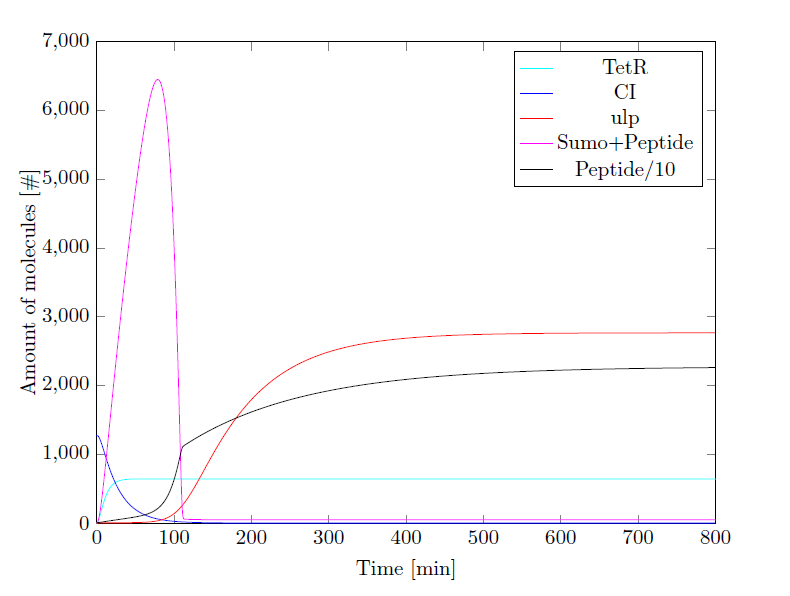
Figure 2: Simulation Results