"
"
Team:Peking/Model
From 2013.igem.org
| Line 315: | Line 315: | ||
<p id="Paragraph13">Letting the differential term on the left handed side equal to zero, the steady state solution of the equations can be solved as following:</p> | <p id="Paragraph13">Letting the differential term on the left handed side equal to zero, the steady state solution of the equations can be solved as following:</p> | ||
| - | <img id=" | + | <img id="model3" src="https://static.igem.org/mediawiki/2013/4/46/Peking_model3.png" /> |
| + | |||
| + | <p id="Title4">Circuit Network 2: </p> | ||
| + | |||
| + | <img id="model4" src="https://static.igem.org/mediawiki/2013/5/54/Peking2013_model4.png" /> | ||
| + | |||
| + | <p id="Paragraph14">Note: For reason same as that described in Circuit Network 1, expression level of A doesn't appear in the equations written above. </p> | ||
| + | |||
| + | <p id="Paragraph15">The steady state solution of the equations can be solved as following: </p> | ||
| + | |||
| + | |||
| + | |||
| + | <img id="model5" src="https://static.igem.org/mediawiki/2013/4/4a/Peking2013_model5.png" /> | ||
| - | |||
| - | |||
</div> | </div> | ||
Revision as of 15:41, 24 September 2013


Model
Introduction
A regular reporter (for example, fluorescent proteins or pigment) can only detect a narrow range of concentration of input signals, (Figure 1) because they mainly possess a Hill-function type dose-response curve. The linear proportion of such a dose-response curve is relatively narrow,causing it sensitive to only a narrow range of input intensity. Thus the regular reporters are not proper devices for quantitative measurement. In order to design a quantitative, economical and convenient aromatics detector, we decided to build a band pass filter.
Selecting Network Topologies
There are a lot of potential band-pass filter topologies with an incoherent feed-forward loop as its core topology. The simplest one is a two-node topology with a positive loop and a negative loop (Fig 1.a). But it’s too difficult to make a transcriptional factor both activator and repressor at the same time.
So we set out to look for topologies with three or more nodes based on two criteria: first, considering functioning mechanisms of real protein regulators, the input node must regulate other nodes in a uniform manner, either all inhibiting or all promoting; second, to lessen the manual work required to construct the circuit, we require both the positive and negative feed-forward loop to contain no more than one internode. In the end, we decided to analyze three topologies in detail, two of them have three nodes and one has four nodes (Fig 1.b, c, d).
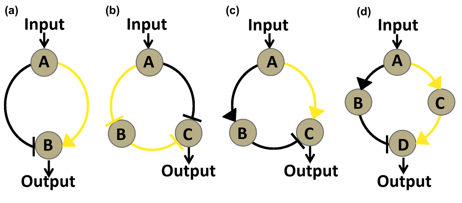
Figure 1.Four kinds of circuit that might form a band-pass filter. (a)Two node circuit. A is the inducible transcriptional factor, B is the reporter GFP. (b)Three node circuit. . A is the inducible repressor, B is a repressor regulated by A, C is the reporter GFP. (c)Three node circuit. . A is the inducible activator, B is a repressor regulated by A, C is the reporter GFP. (d)Four node circuit. . A is the inducible activator, B is a repressor regulated by A, C is the activator regulated by A, D is the reporter GFP.
ODE Analysis of Circuit Networks
After determining three typical circuit networks that might function as band-pass filters, we used Ordinary Differential Equations (ODE) to analyze the three topology and their parameter preferences.
Our ODE model of the circuit networks was established based on the following assumptions:
1. Only transcription and translation process is taken into consideration. The equations only contain accumulation and degradation of the proteins represented by the nodes.
2. The interactions between nodes are described using Hill functions. We multiplied the Hill functions describing the individual regulating effects of activator and repressor in order to simulate the synergic regulating effect of the two transcription factors when bound to the same promoter.
3. The protein represented by the input node is constitutively expressed at a fixed level.
4. Leakage is present only in the expression of reporter gene (output node).
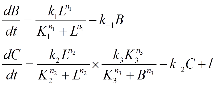
The ODE equations we used to simulate the three circuit networks are listed as following:
Circuit Network 1:

Note: Since A is expressed at a fixed level, its influence on the network can be absorbed into other constants in the model, so it doesn't appear in the equations written above.
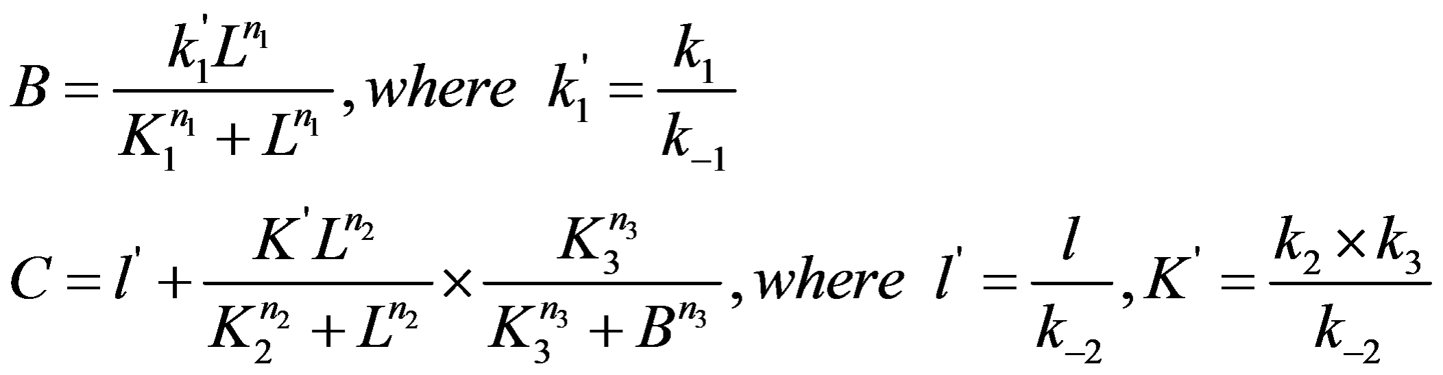
Letting the differential term on the left handed side equal to zero, the steady state solution of the equations can be solved as following:
Letting the differential term on the left handed side equal to zero, the steady state solution of the equations can be solved as following:

Circuit Network 2:
Note: For reason same as that described in Circuit Network 1, expression level of A doesn't appear in the equations written above.
The steady state solution of the equations can be solved as following: