Team:Newcastle/Modelling/Hbsu Fusion Protein
From 2013.igem.org

Contents |
HBsu-xFP
The BioBrick we created to visualize genome shuffling is under the control of an IPTG-inducible promoter. Normally a repressor protein is bound to it, preventing gene transcription. However IPTG can binds to the repressor, changing its shape and removing it from the promoter, allowing expression and production of HBsu-xFP. Using BioNetGen we attempted to model this system, and see if we could predict the time it took for gene expression to start, given initial concentrations of IPTG. As we had no access to Western Blotting or other techniques to determine protein production experimentally, we also attempted to link fluorescence to the average molecule numbers our model predicted.


The Model
The model can be split into a few sections. The main part is the binding of 2 IPTG molecules to the protein repressing the BioBrick promoter, the repressor leaving the DNA, allowing gene expression.
IPTG(p) + DNA(prot!0,promoter~0).Rep(dna!0,a) <-> IPTG(p) +
DNA(prot!0,promoter~0).Rep(dna!0,a!1).IPTG(p!1)
This represents the bonding of both IPTG molecules to the repressor
IPTG(p!1).Rep(a!1,a!2,dna!3).IPTG(p!2).DNA(prot!3,promoter~0) ->
IPTG(p!1).Rep(a!1,a!2,dna).IPTG(p!2)+ DNA(prot,promoter~1)
Here the repressor leaves the operator region upstream of the BioBrick. Note that DNA(promoter~0) has changed to DNA(promoter~1) signifying that the DNA can now be transcribed.
Other repressor protein not bound to the DNA will also be attacked by IPTG, preventing them from binding to the now free DNA. This is represented by the reaction rule:
IPTG(p) + Rep(dna,a) <-> IPTG(p!1).Rep(a!1,dna)
Free repressor can still bind to the DNA however:
DNA(prot,promoter~1) + Rep(dna,a,a) ->
DNA(prot!0,promoter~0).Rep(dna!0,a,a)
The next stage is the transcription and translation of the HBsu-xFP gene:
DNA(prot,promoter~1) -> DNA(prot,promoter~1) + hbsu_mRNA()
hbsu_mRNA() -> hbsu_mRNA() + HBsu()
The protein will however slowly degrade:
HBsu() -> 0
Before binding to the repressor, IPTG must first diffuse into the cell:
IPTG_outside(a) -> IPTG(p)
Finally the repressor is constantly being produced and degraded. The lac repressor is a dimer-dimer. Thus the mRNA codes for a monomer, which dimerizes, and dimerizes again:
0 -> Rep_mRNA()
Rep_mRNA() -> Rep_mono()
Rep_mono() + Rep_mono()  <-> Rep_dimer()
Rep_dimer() + Rep_dimer() <-> Rep(dna,a,a)
Rep_mRNA()  ->0
Parameters can be found in the .txt file, and are based on cdhbdhjbvhjvbsdjhcba The network diagram for this model is in the gallery near the top of this page, as 'contact map'.
The BioNetGen file (in .txt format, if you'd like to try it out just change the extension to .bngl)
Methods
The model was simulated stochastically 25 times at 6 different initial concentrations of IPTG: 0mM, 0.05mM, 0.1mM 0.2mM, 0.4mM and 0.8mM, as these were the concentrations we used experimentally. The results for at each concentration were aggregated and averaged using R and graphed against the measured intensity of the HBsu-sfGFP/RFP fluorescence at each concentration.
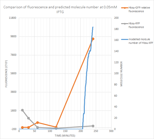
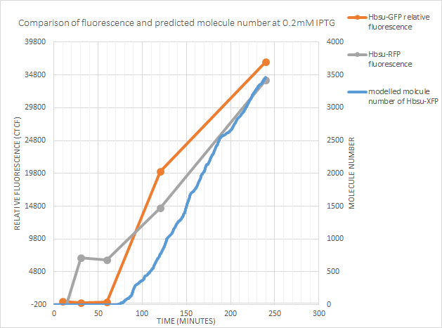
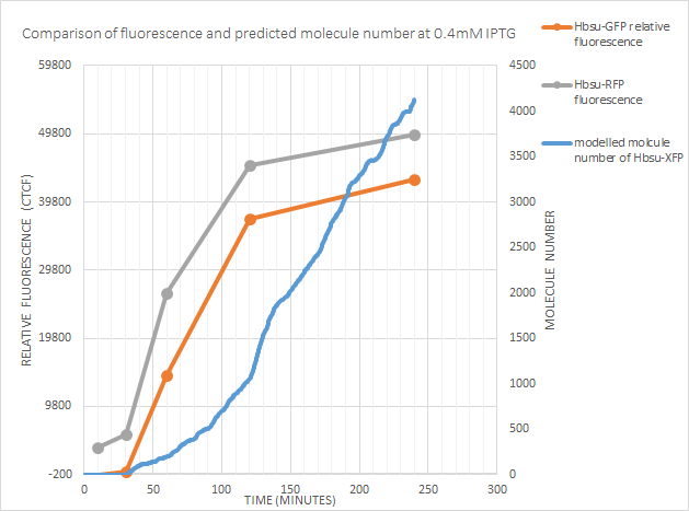
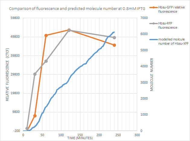
This fluorescence was calculated using [http://rsbweb.nih.gov/ij/ imageJ]. As shown in Figure (), initially we used the line selection tool to drew across the cell and measure its mean fluorescence. With mean background fluorescence then measured as a control. To get a Corrected Total Cell Fluorescence (CTCF) for each cell, the mean background fluorescence was deducted from the mean fluorescence of the cell. This was done for 20 cells at each IPTG concentration. This showed that our model predicted the time taken for IPTG to bind to the repressor and allow expression of the BioBrick with reasonable accuracy. Fluorescence was measured experimentally at 0,10,30,60,120 and 240 minutes. Expression of the BioBrick began roughly when expected, although the model was less reliable at lower concentrations of IPTG, often predicting no expression within 240 minutes at 0.05mM IPTG. The stochasticity also increased at lower IPTG concentrations (until no expression was predicted), though this is to be expected
Results
0mM IPTG
Even with no IPTG fluorescence was recirded. This could be due to small amounts of transcription despite the presence of the repressor- which does happen. However negative fluorescence results are recorded. This shows that our method of measuring fluorescence wasn't perfectly accurate.
0.05mM IPTG
sfGFP fluorescence (and thus protein production) began at some point between the recorded 100 minutes and 240 minutes. The model predicts gene expression began around 205 minutes after exposure to IPTG, which lies between these values. However RFP fluorescence is negligible. The model predicts fewer than 200 molecules of the protein produced, so this isn’t too suprising as the RFP signal is weaker than the sfGFP
0.1mM IPTG
sfGFP fluorescence began between 60-120 minutes, and the model predicted gene expression after around 100 minutes. From the fluorescence data it might be expected for gene expression to occur a little earlier, but is a decent approximation. Predicted molecule number correlates well with RFP fluorescence at this concentration.
0.2mM IPTG
At 0.2mM the predicted time after exposure to IPTG until expression correlates with both RFP and GFP fluorescence.
0.4mM IPTG
The model accurately predicts the time of expression. Of note however is the increase in fluorescence dropping off after 120 minutes, whilst the model predicts molecule number continuing to increase. This could be because:
- The model should have the HBsu-xFP degrade more quickly. The half-life of HBsu is 18-24 hours, however our new protein could be lower.
- The cell may be controlling the gene expression via some form of negative feedback pathway. This may be as
fluorescence proteins are large and
- The protein could be toxic at higher concentrations
- The relationship between the protein and fluorescence is not linear
We did not have the time or resources to test these hypothesis', but ideally tests would be done and if necessary the model tweaked
0.8mM IPTG
Once again the point of time at which expression began was well predicted by the model. However after 120 minutes fluorescence actually decreased! This could just be due to the intrinsic variabilty of the fluorescent measurements, or could be due to one of the possibilities considered above
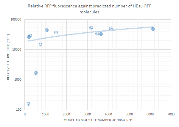
Fluorescence was then plotted against molecule number for each non-0 molecule number result. This showed that there is a positive correlation between molecule number and log(fluorescence). The first graph below is for HBsu-GFP, and underneath that HBsu-RFP.
References
 "
"

