"
"
Team:Tokyo Tech/Experiment/Crosstalk Circumvention Assay
From 2013.igem.org
| (64 intermediate revisions not shown) | |||
| Line 1: | Line 1: | ||
{{tokyotechmenudark}} | {{tokyotechmenudark}} | ||
| - | |||
| - | |||
<div id="text-area"><br> | <div id="text-area"><br> | ||
| - | + | <div class="box" id="title"> | |
| + | <p style="line-height:0em; text-indent:0em;">Crosstalk Circumvention Assay</p> | ||
| + | </div> | ||
| + | <div class="box"> | ||
| + | <h1>1. Introduction </h1> | ||
| - | |||
| - | |||
| - | |||
| - | |||
<h2> | <h2> | ||
| - | <p> | + | <p>Of course, if you want to avoid crosstalk, you have to search ideas for crosstalk circumvention. However, you must make conditions without affecting system wide, or without changing the basis of system in the idea for improvement. This is because "crosstalk circumvention by changing system-wide" is the same meaning as saying "crosstalk circumvention only in that circuit". For example, when you want to avoid crosstalk in the circuit on the basis of toggle switch system, you should think that it is nonsense to avoid crosstalk by abandoning toggle switch system. You should think it's nice to avoid crosstalk without abandoning toggle switch system. In short, I hope crosstalk circumvention system is applicable to various circuits. Based on this view, we planned the following idea and experimentation. |
</p> | </p> | ||
</h2> | </h2> | ||
| - | < | + | <h1>2. Summary of the experiment </h1> |
| - | </ | + | <h2><p>Our purpose is to check whether or not <i>lux/tet</i> hybrid promoter would be repressed when 3OC12HSL-LasR complex and protein TetR exist. We tried to compare the frequency of crosstalk in the presence or absence of the aTc, the TetR inhibitor. |
| - | <h2> | + | |
| - | <p>We | + | |
</p> | </p> | ||
| - | <p> | + | <p>We prepared six conditions as follow. |
| + | <blockquote> | ||
| + | <li>E-1) Culture containing crosstalk circumvention system cell with 3OC6HSL induction | ||
| + | <li>E-2) Culture containing crosstalk circumvention system cell with 3OC12HSL induction | ||
| + | <li>E-3) Culture containing crosstalk circumvention system cell with DMSO (no induction) | ||
| + | <br><br> | ||
| + | <li>F-1) Culture containing crosstalk circumvention system cell with 3OC6HSL and aTc induction | ||
| + | <li>F-2) Culture containing crosstalk circumvention system cell with 3OC12HSL and aTc induction | ||
| + | <li>F-3) Culture containing crosstalk circumvention system cell with DMSO and aTc (no induction) | ||
| + | <br><br> | ||
| + | <li>Positive control and negative control are similarly operated. | ||
| + | </blockquote></p> | ||
| + | <p> | ||
| + | We also screened the concentration of 3OC6HSL and aTc, and examined activation of the crosstalk circumvention system circuit. Then we determined the transfer function of 3OC6HSL-LuxR complex by least squares method fitting and introduced into our [https://2013.igem.org/Team:Tokyo_Tech/Modeling/Crosstalk_Circumvention#2-3._Parameter_optimization_and_simulation modeling]. | ||
</p> | </p> | ||
</h2> | </h2> | ||
| - | < | + | <h1>3. Prediction </h1> |
| - | </ | + | |
<h2> | <h2> | ||
| - | <p> | + | <p> |
| + | aTc weakens the affinity of TetR for <i>tetO</i>. Therefore, if the GFP expression level of the cells we added 3OC6HSL+aTc into was higher than that of the cells we added only 3OC6HSL into, it proved that <i>lux/tet</i> hybrid promoter is repressed by TetR. Similarly, if the GFP expression level of the cells we added 3OC12HSL+aTc into was higher than that of the cells we added only 3OC12HSL into, it proved that the crosstalk can be suppressed by TetR and the hybrid promoter. | ||
</p> | </p> | ||
</h2> | </h2> | ||
| - | <h3> | + | <h1>4. Materials and Methods </h1> |
| - | </h3> | + | <h3>4-1. Construction </h3> |
| + | <h2><p> | ||
| + | On the previous assay, we also confirmed crosstalk, which 3OC12HSL-LasR complex activates not only <i>las</i> promoter but also <i>lux</i> promoter (Gray KM et al., 1994). We came up with an idea that crosstalk can be suppressed if <i>lux/tet</i> hybrid promoter is inhibited by protein TetR when 3OC12HSL-LasR complex exists. We replaced <i>lux</i> promoter with <i>lux/tet</i> hybrid promoter. What we have to do in this step is to confirm <i>lux/tet</i> hybrid promoter works correctly as a part of the system. Therefore, we tried to make a simple crosstalk circumvention system (Fig. 3-2-1). <i>luxR</i>, <i>tetR</i>, and <i>lasR</i> are under constitutive promoter. | ||
| + | </p> | ||
| + | [[Image:Titech2013_CrosstalkCircumventionAssay_3-2_1.jpg|500px|thumb|center|Fig. 3-2-1. Circuit of the simple crosstalk circumvention system]] | ||
| + | <p>Because of the unexpected restriction enzyme binding site on the regulator plasmid, we had to place <i>luxR</i> and <i>tetR</i> on the regulator plasmid, and <i>lux/tet</i> hybrid promoter, <i>GFP</i> and <i>lasR</i> on the reporter plasmid (Fig. 3-2-2). | ||
| + | </p> | ||
| + | [[Image:Titech2013_CrosstalkCircumventionAssay_3-2_2.jpg|500px|thumb|center|Fig. 3-2-2. The actual circuit]] | ||
| + | <p> | ||
| + | To construct the circuit in above figure (Fig. 3-2-2), we ligated Pcon-RBS-<i>lasR</i>-TT ([http://parts.igem.org/Part:BBa_K553003 BBa_K553003]) and Plux/tet-RBS-<i>GFP</i>-TT ([http://parts.igem.org/Part:BBa_K934025 BBa_K934025]) as the reporter plasmid. We used Pcon-RBS-<i>luxR</i>-TT-Ptrc-RBS-<i>tetR</i>-TT as the regulator plasmid. | ||
| + | <blockquote> | ||
| + | <li>Reporter: pSB6A1-Pcon-<i>lasR</i>-Plux/tet-<i>GFP</i> / Regulator: pSB3K3-Pc-<i>luxR</i>-Ptrc-<i>tetR</i> (JM2.300)...sample<br> | ||
| + | <li>pSB6A1-Ptet-<i>GFP</i> (JM2.300)…positive control<br> | ||
| + | <li>pSB6A1-Promoterless-<i>GFP</i> (JM2.300)…negative control<br> | ||
| + | </blockquote></p> | ||
| + | </h2> | ||
| + | <h3>4-2. Strain </h3> | ||
<h2> | <h2> | ||
| - | < | + | JM2.300<br><br> |
| - | </ | + | </h2> |
| - | + | ||
| - | + | ||
| - | + | ||
| + | <h3>4-3. Protocol </h3> | ||
| + | <h2> | ||
| + | 1. O/N -> FC -> Induction<br> | ||
| + | <p><blockquote>1.1 Prepare overnight culture of each cell (GFP posi, GFP nega, sample) at 37°C for 12 h.<br> (=> O/N) | ||
| + | </blockquote></p> | ||
| + | <p><blockquote>1.2 Take 30 µL (from GFP posi, GFP nega, sample) of the overnight culture of inducer cell into<br> LB (3 mL) + antibiotics (Amp 50 µg/mL+ Kan 30 µg/mL).<br> (=> Fresh Culture) | ||
| + | </blockquote></p> | ||
| + | <p><blockquote>1.3 Incubate the flesh culture of cells (GFP posi, GFP nega, sample) until the observed OD600 reaches around 0.50. | ||
| + | </blockquote></p> | ||
| + | <p><blockquote>1.4a Take 30 µL each cell suspensions (GFP posi , GFP nega , sample) into<br> | ||
| + | </blockquote></p> | ||
| + | <blockquote> | ||
| + | <p><blockquote> | ||
| + | LB (3 mL) + antibiotics (Amp 50 µg/mL + Kan 30 µg/mL)<br> + 5 µM 3OC6HSL (3 µL), | ||
| + | </blockquote></p> | ||
| + | <p><blockquote> | ||
| + | LB (3 mL) + antibiotics (Amp 50 µg/mL + Kan 30 µg/mL)<br> + 5 µM 3OC6HSL (3 µL) + 0.05 µg/mL aTc (3 µL), | ||
| + | </blockquote></p> | ||
| + | <p><blockquote> | ||
| + | LB (3 mL) + antibiotics (Amp 50 µg/mL + Kan 30 µg/mL)<br> + 5 µM 3OC12HSL (3 µL), | ||
| + | </blockquote></p> | ||
| + | <p><blockquote> | ||
| + | LB (3 mL) + antibiotics (Amp 50 µg/mL+ Kan 30 µg/mL)<br> + 5 µM 3OC12HSL (3 µL)+ 0.05 mg/mL aTc (3 µL), | ||
| + | </blockquote></p> | ||
| + | <p><blockquote> | ||
| + | LB (3 mL) + antibiotics (Amp 50 µg/mL + Kan 30 µg/mL)<br> + 5 µM DMSO (3 µL), | ||
| + | </blockquote></p> | ||
| + | <p><blockquote> | ||
| + | LB (3 mL) + antibiotics (Amp 50 µg/mL + Kan 30 µg/mL)<br> + 5 µM DMSO (3 µL) + 0.05 mg/mL aTc (3 µL). | ||
| + | </blockquote></p> | ||
| + | </blockquote> | ||
| + | |||
| + | <p><blockquote>1.4b Take 30 µL each cell suspensions (GFP posi , GFP | ||
| + | nega , sample) into | ||
| + | <br> | ||
| + | </blockquote></p> | ||
| + | <blockquote> | ||
| + | <p><blockquote> | ||
| + | LB (3 mL) + antibiotics (Amp 50 µg/mL + Kan 30 µg/mL)<br>+ C6 (3 µL) + aTc (3 µL) … inducer concentration for each sample is shown in below (Fig 3-2-3) | ||
| + | </blockquote></p> | ||
| + | </blockquote> | ||
| + | <br> | ||
| + | <table align="center" border="1"> | ||
| + | <tr align="center"> | ||
| + | <td></td> | ||
| + | <td colspan=7> | ||
| + | aTc (µg/mL) | ||
| + | </td> | ||
| + | </tr> | ||
| + | <tr align="center"> | ||
| + | <td rowspan=8 width="70"> | ||
| + | <br><br><br> | ||
| + | <p style="text-indent: 0em; | ||
| + | padding-left: 0;">C6 (nM)</p> | ||
| + | </td> | ||
| + | <td width="60"><br></td><td width="60">0</td><td width="60">0.05</td><td width="60">0.15</td><td width="60">0.5</td><td width="60">1.5</td><td width="60">5</td> | ||
| + | </tr> | ||
| + | <tr align="center"><td>0</td><td>No. 1</td><td>No. 2</td><td>No. 3</td><td>No. 4</td><td>No. 5</td><td>No. 6</td></tr> | ||
| + | <tr align="center"><td>0.3</td><td>No. 7</td><td>No. 8</td><td>No. 9</td><td>No. 10</td><td>No. 11</td><td>No. 12</td></tr> | ||
| + | <tr align="center"><td>1</td><td>No. 13</td><td>No. 14</td><td>No. 15</td><td>No. 16</td><td>No. 17</td><td>No. 18</td></tr> | ||
| + | <tr align="center"><td>3</td><td>No. 19</td><td>No. 20</td><td>No. 21</td><td>No. 22</td><td>No. 23</td><td>No. 24</td></tr> | ||
| + | <tr align="center"><td>10</td><td>No. 25</td><td>No. 26</td><td>No. 27</td><td>No. 28</td><td>No. 29</td><td>No. 30</td></tr> | ||
| + | <tr align="center"><td>30</td><td>No. 31</td><td>No. 32</td><td>No. 33</td><td>No. 34</td><td>No. 35</td><td>No. 36</td></tr> | ||
| + | <tr align="center"><td>100</td><td>No. 37</td><td>No. 38</td><td>No. 39</td><td>No. 40</td><td>No. 41</td><td>No. 42</td></tr> | ||
| + | </table> | ||
| + | <center>Fig. 3-2-3. Inducer concentration for each sample</center> | ||
| + | <p><blockquote> | ||
| + | 1.5 Incubate all samples (6 samples X 6 kinds of culture = 36 samples) for another 4 h at 37°C. <br> (=> Induction) | ||
| + | </blockquote></p> | ||
</h2> | </h2> | ||
| - | |||
| - | |||
<h2> | <h2> | ||
| - | <p> | + | 2. Measurement (Flow cytometer)<br> |
| + | <p>2.1 Measure all samples' OD600.</p> | ||
| + | <p>2.2 Dilute all samples with 1X PBS to keep OD600 in the range from 0.2 to 0.5. | ||
</p> | </p> | ||
| - | <p>( | + | <p>2.3 Take 1 mL (from all samples) into disposable tube (for flow cytometer). |
</p> | </p> | ||
| - | <p> | + | <p>2.4 Centrifuge them at 9,000g, 4°C, 1 min. and take their supernatant away. |
</p> | </p> | ||
| - | <p> | + | <p>2.5 Suspend all samples with 1 mL 1X PBS. |
</p> | </p> | ||
| - | + | <p>2.6 Measure all samples. | |
| - | <p> | + | |
</p> | </p> | ||
| - | <p> | + | <p>2.7 Save and organize data. |
</p> | </p> | ||
| - | |||
| - | |||
| - | |||
| - | |||
| - | |||
| - | |||
| - | |||
| - | |||
| - | |||
| - | |||
</h2> | </h2> | ||
| - | < | + | <h1>5. Results of the assay </h1> |
| - | </ | + | |
<h2> | <h2> | ||
| - | + | [[Image:Titech2013_CrosstalkCircumventionAssay_3-2_3.jpg|500px|thumb|center|Fig. 3-2-4. Crosstalk circumvention results]] | |
| - | + | ||
</h2> | </h2> | ||
| - | < | + | <h2><p>Fig. 3-2-4 shows the following. <i>lux/tet</i> hybrid promoter is repressed by TetR in the presence of 3OC6HSL-LuxR complex. Similarly, <i>lux/tet</i> hybrid promoter is repressed by TetR in the presence of 3OC12HSL-LasR complex. In brief, results from E-1) and F-1) are similar to those from E-2) and F-2). Therefore, the crosstalk circumvention experiment succeeded. |
| - | </ | + | </p></h2> |
<h2> | <h2> | ||
| - | + | [[Image:Titech2013_CrosstalkCircumventionAssay_3-2_5.jpg|500px|thumb|center|Fig. 3-2-5. Activation of the crosstalk circumvention system circuit]] | |
| - | </ | + | </h2> |
| - | <p>2. | + | <h2><p>Fig. 3-2-5 shows activation of the crosstalk circumvention system circuit. It shows transition of the fluorescence intensity of GFP. It indicates that the concentration of C6 saturates between 10 mM and 30 mM. |
| - | + | ||
| - | + | ||
</p> | </p> | ||
</h2> | </h2> | ||
| - | + | <h1>6. Reference </h1> | |
| - | + | <h2> | |
| - | + | <OL><LI> | |
| + | Gray KM, Passador L (1994) Interchangeability and specificity of components from the quorum-sensing regulatory systems of Vibrio fischeri and Pseudomonas aeruginosa. Journal of bacteriology 176(10): 3076–3080.</LI></OL> | ||
| + | </h2> | ||
</div><br> | </div><br> | ||
| + | <html><div align="center"><a href="https://2013.igem.org/Team:Tokyo_Tech/Experiment/Crosstalk_Circumvention_Assay#top"><img src="https://static.igem.org/mediawiki/2013/f/f0/Titeh2013_backtotop.png" width="200px"></a></div></html> | ||
</div> | </div> | ||
| - | |||
| - | |||
Latest revision as of 03:05, 29 October 2013

Crosstalk Circumvention Assay
Contents |
1. Introduction
Of course, if you want to avoid crosstalk, you have to search ideas for crosstalk circumvention. However, you must make conditions without affecting system wide, or without changing the basis of system in the idea for improvement. This is because "crosstalk circumvention by changing system-wide" is the same meaning as saying "crosstalk circumvention only in that circuit". For example, when you want to avoid crosstalk in the circuit on the basis of toggle switch system, you should think that it is nonsense to avoid crosstalk by abandoning toggle switch system. You should think it's nice to avoid crosstalk without abandoning toggle switch system. In short, I hope crosstalk circumvention system is applicable to various circuits. Based on this view, we planned the following idea and experimentation.
2. Summary of the experiment
Our purpose is to check whether or not lux/tet hybrid promoter would be repressed when 3OC12HSL-LasR complex and protein TetR exist. We tried to compare the frequency of crosstalk in the presence or absence of the aTc, the TetR inhibitor.
We prepared six conditions as follow.
E-1) Culture containing crosstalk circumvention system cell with 3OC6HSL induction E-2) Culture containing crosstalk circumvention system cell with 3OC12HSL induction E-3) Culture containing crosstalk circumvention system cell with DMSO (no induction)
F-1) Culture containing crosstalk circumvention system cell with 3OC6HSL and aTc induction F-2) Culture containing crosstalk circumvention system cell with 3OC12HSL and aTc induction F-3) Culture containing crosstalk circumvention system cell with DMSO and aTc (no induction)
Positive control and negative control are similarly operated.
We also screened the concentration of 3OC6HSL and aTc, and examined activation of the crosstalk circumvention system circuit. Then we determined the transfer function of 3OC6HSL-LuxR complex by least squares method fitting and introduced into our modeling.
3. Prediction
aTc weakens the affinity of TetR for tetO. Therefore, if the GFP expression level of the cells we added 3OC6HSL+aTc into was higher than that of the cells we added only 3OC6HSL into, it proved that lux/tet hybrid promoter is repressed by TetR. Similarly, if the GFP expression level of the cells we added 3OC12HSL+aTc into was higher than that of the cells we added only 3OC12HSL into, it proved that the crosstalk can be suppressed by TetR and the hybrid promoter.
4. Materials and Methods
4-1. Construction
On the previous assay, we also confirmed crosstalk, which 3OC12HSL-LasR complex activates not only las promoter but also lux promoter (Gray KM et al., 1994). We came up with an idea that crosstalk can be suppressed if lux/tet hybrid promoter is inhibited by protein TetR when 3OC12HSL-LasR complex exists. We replaced lux promoter with lux/tet hybrid promoter. What we have to do in this step is to confirm lux/tet hybrid promoter works correctly as a part of the system. Therefore, we tried to make a simple crosstalk circumvention system (Fig. 3-2-1). luxR, tetR, and lasR are under constitutive promoter.

Because of the unexpected restriction enzyme binding site on the regulator plasmid, we had to place luxR and tetR on the regulator plasmid, and lux/tet hybrid promoter, GFP and lasR on the reporter plasmid (Fig. 3-2-2).

To construct the circuit in above figure (Fig. 3-2-2), we ligated Pcon-RBS-lasR-TT ([http://parts.igem.org/Part:BBa_K553003 BBa_K553003]) and Plux/tet-RBS-GFP-TT ([http://parts.igem.org/Part:BBa_K934025 BBa_K934025]) as the reporter plasmid. We used Pcon-RBS-luxR-TT-Ptrc-RBS-tetR-TT as the regulator plasmid.
Reporter: pSB6A1-Pcon-lasR-Plux/tet-GFP / Regulator: pSB3K3-Pc-luxR-Ptrc-tetR (JM2.300)...sample
pSB6A1-Ptet-GFP (JM2.300)…positive control
pSB6A1-Promoterless-GFP (JM2.300)…negative control
4-2. Strain
JM2.300
4-3. Protocol
1. O/N -> FC -> Induction
1.1 Prepare overnight culture of each cell (GFP posi, GFP nega, sample) at 37°C for 12 h.
(=> O/N)
1.2 Take 30 µL (from GFP posi, GFP nega, sample) of the overnight culture of inducer cell into
LB (3 mL) + antibiotics (Amp 50 µg/mL+ Kan 30 µg/mL).
(=> Fresh Culture)
1.3 Incubate the flesh culture of cells (GFP posi, GFP nega, sample) until the observed OD600 reaches around 0.50.
1.4a Take 30 µL each cell suspensions (GFP posi , GFP nega , sample) into
LB (3 mL) + antibiotics (Amp 50 µg/mL + Kan 30 µg/mL)
+ 5 µM 3OC6HSL (3 µL),LB (3 mL) + antibiotics (Amp 50 µg/mL + Kan 30 µg/mL)
+ 5 µM 3OC6HSL (3 µL) + 0.05 µg/mL aTc (3 µL),LB (3 mL) + antibiotics (Amp 50 µg/mL + Kan 30 µg/mL)
+ 5 µM 3OC12HSL (3 µL),LB (3 mL) + antibiotics (Amp 50 µg/mL+ Kan 30 µg/mL)
+ 5 µM 3OC12HSL (3 µL)+ 0.05 mg/mL aTc (3 µL),LB (3 mL) + antibiotics (Amp 50 µg/mL + Kan 30 µg/mL)
+ 5 µM DMSO (3 µL),LB (3 mL) + antibiotics (Amp 50 µg/mL + Kan 30 µg/mL)
+ 5 µM DMSO (3 µL) + 0.05 mg/mL aTc (3 µL).
1.4b Take 30 µL each cell suspensions (GFP posi , GFP nega , sample) into
LB (3 mL) + antibiotics (Amp 50 µg/mL + Kan 30 µg/mL)
+ C6 (3 µL) + aTc (3 µL) … inducer concentration for each sample is shown in below (Fig 3-2-3)
|
aTc (µg/mL) |
|||||||
|
C6 (nM) |
0 | 0.05 | 0.15 | 0.5 | 1.5 | 5 | |
| 0 | No. 1 | No. 2 | No. 3 | No. 4 | No. 5 | No. 6 | |
| 0.3 | No. 7 | No. 8 | No. 9 | No. 10 | No. 11 | No. 12 | |
| 1 | No. 13 | No. 14 | No. 15 | No. 16 | No. 17 | No. 18 | |
| 3 | No. 19 | No. 20 | No. 21 | No. 22 | No. 23 | No. 24 | |
| 10 | No. 25 | No. 26 | No. 27 | No. 28 | No. 29 | No. 30 | |
| 30 | No. 31 | No. 32 | No. 33 | No. 34 | No. 35 | No. 36 | |
| 100 | No. 37 | No. 38 | No. 39 | No. 40 | No. 41 | No. 42 | |
1.5 Incubate all samples (6 samples X 6 kinds of culture = 36 samples) for another 4 h at 37°C.
(=> Induction)
2. Measurement (Flow cytometer)
2.1 Measure all samples' OD600.
2.2 Dilute all samples with 1X PBS to keep OD600 in the range from 0.2 to 0.5.
2.3 Take 1 mL (from all samples) into disposable tube (for flow cytometer).
2.4 Centrifuge them at 9,000g, 4°C, 1 min. and take their supernatant away.
2.5 Suspend all samples with 1 mL 1X PBS.
2.6 Measure all samples.
2.7 Save and organize data.
5. Results of the assay

 Fig. 3-2-4. Crosstalk circumvention results

Fig. 3-2-4 shows the following. lux/tet hybrid promoter is repressed by TetR in the presence of 3OC6HSL-LuxR complex. Similarly, lux/tet hybrid promoter is repressed by TetR in the presence of 3OC12HSL-LasR complex. In brief, results from E-1) and F-1) are similar to those from E-2) and F-2). Therefore, the crosstalk circumvention experiment succeeded.
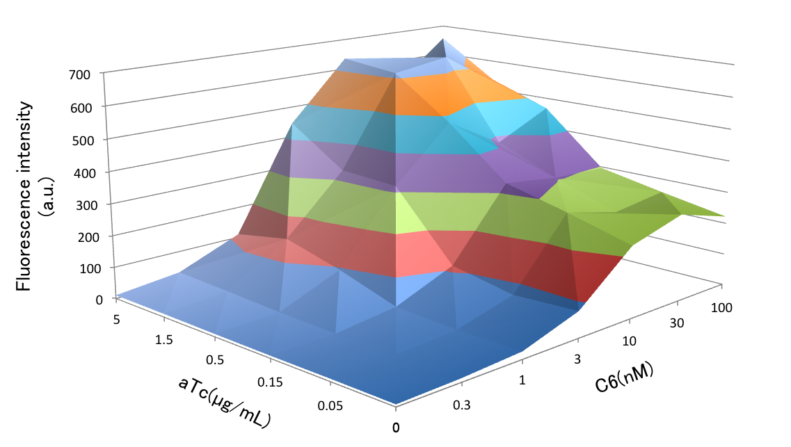 Fig. 3-2-5. Activation of the crosstalk circumvention system circuit

Fig. 3-2-5 shows activation of the crosstalk circumvention system circuit. It shows transition of the fluorescence intensity of GFP. It indicates that the concentration of C6 saturates between 10 mM and 30 mM.
6. Reference
-
Gray KM, Passador L (1994) Interchangeability and specificity of components from the quorum-sensing regulatory systems of Vibrio fischeri and Pseudomonas aeruginosa. Journal of bacteriology 176(10): 3076–3080.