Team:TU-Munich/Results/Implementation
From 2013.igem.org
PSchneider (Talk | contribs) (→Implementation of a Plant Biofilter) |
PSchneider (Talk | contribs) |
||
| Line 7: | Line 7: | ||
==Implementation of a Plant Biofilter== | ==Implementation of a Plant Biofilter== | ||
| - | + | How does a '''biofilter''' look like? | |
| + | To face this question we considered the '''requirements''' for a moss filter and took a look at '''existing solutions'''. We talked to Prof. Dr.-Ing. Clemens Posten, who is head of the Institute of bioprocess engineering in Karlsruhe. So we were shown the institutes's bioreactors and Prof. Posten gave us an idea how a '''symbiosis''' between plant and technology can look like. Although his institute mainly works with algae, two solutions became apparent as sensible. The '''tube reactor''' mainly consists of glass tubes in which the plant is grown. The '''open pond''' model is a meander-shaped pond or slowly floating stream. | ||
| Line 70: | Line 71: | ||
<br><br> | <br><br> | ||
| + | At least there are problems both reactor types don't solve. In both cases upscaling involves a great deal of expense. | ||
| + | The '''tube reactor''' guarantees a big '''contact surface''' between water and moss which is an asset to the filter properties, but the '''carbon dioxide exchange''' is a major problem due to the lack of water-air through mix. To manage big scale filtering on an appropriate area it's inevitable to stack the tubes. That makes extra lighting necessary. | ||
| + | The '''open pond''' model brings along a smaller water-moss surface, therefore the filter properties may suffer and a '''wider area''' is needed. As opposed to the tube reactor the costs are lower and there are no air exchange problems to face. | ||
| + | Slightly we return to the question how a '''biofilter''' could look like. | ||
| + | It has to be a solution that can be implemented in '''any scale'''. The '''costs''' must be kept as low as possible. Additionally the '''energy consumption''' and '''maintenance''' must be kept to a absolute minimum to make it universally usable. | ||
| + | |||
| + | Such a solution has to be '''engineered''' cleverly. Robust to environmental influences, expendable, modular and handy, even when in use. It must provide an ideal environment for the moss to grow and set off an alert if such a setting is no longer provided. | ||
| + | |||
| + | Our answer to that is the '''PhyscoFilter pod'''. | ||
Revision as of 13:57, 30 September 2013
Implementation of a Plant Biofilter
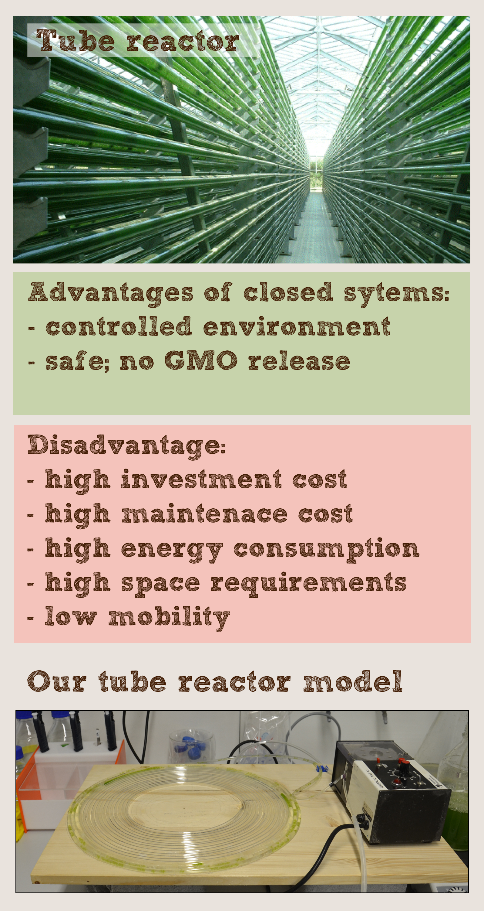
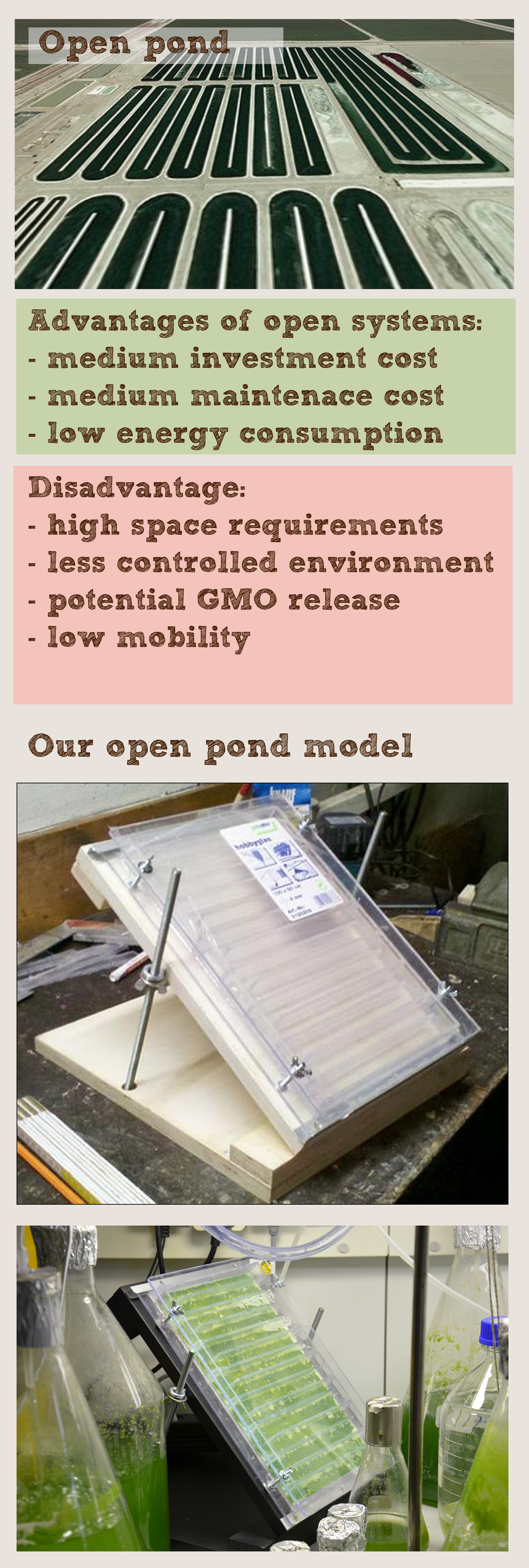
How does a biofilter look like? To face this question we considered the requirements for a moss filter and took a look at existing solutions. We talked to Prof. Dr.-Ing. Clemens Posten, who is head of the Institute of bioprocess engineering in Karlsruhe. So we were shown the institutes's bioreactors and Prof. Posten gave us an idea how a symbiosis between plant and technology can look like. Although his institute mainly works with algae, two solutions became apparent as sensible. The tube reactor mainly consists of glass tubes in which the plant is grown. The open pond model is a meander-shaped pond or slowly floating stream.
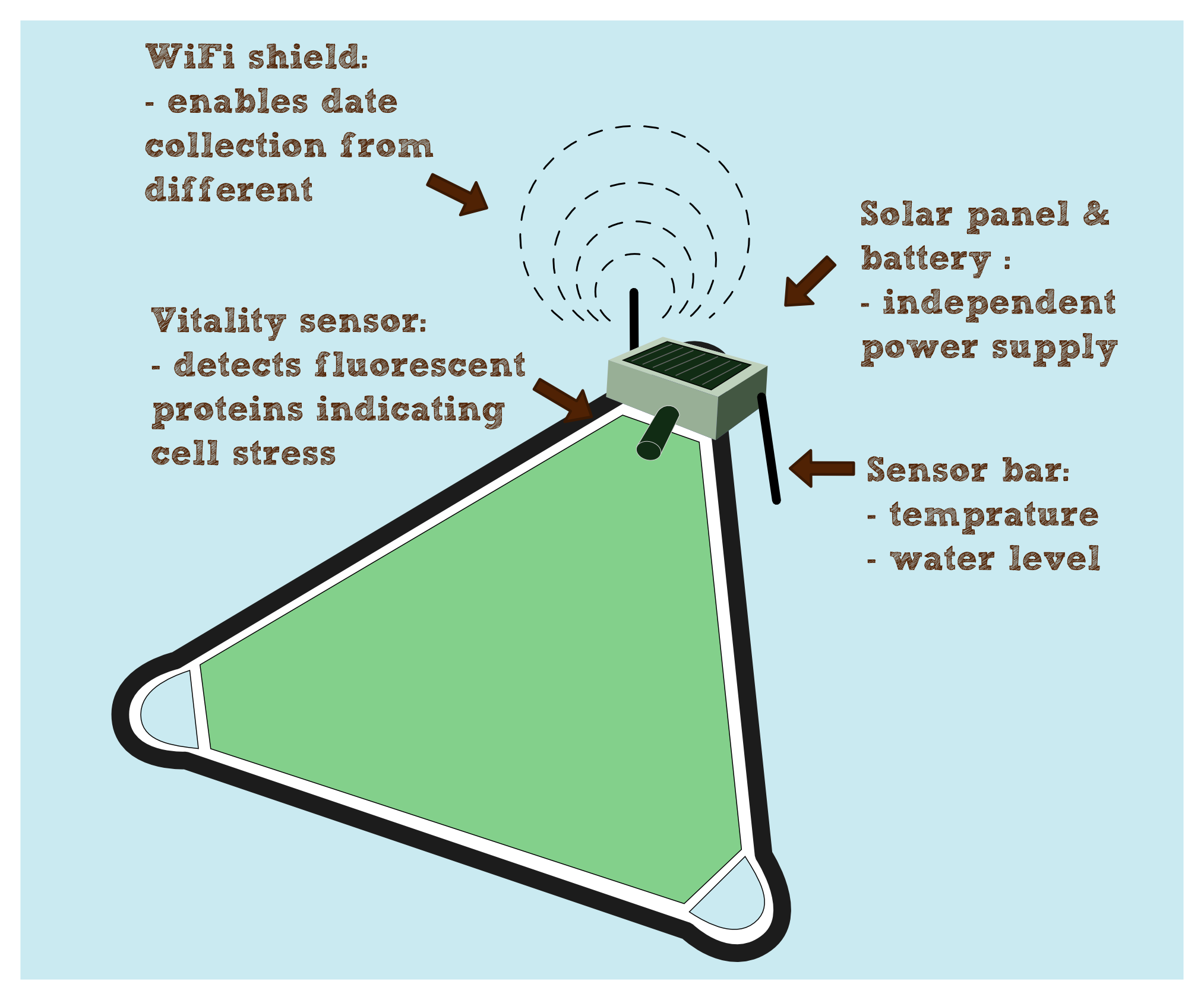
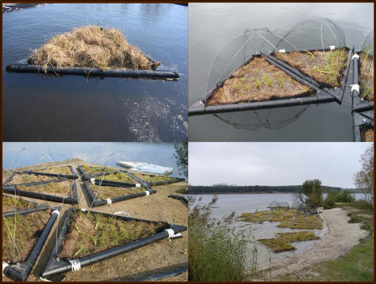
Our swimming PhyscoFilter Prototype pod
At least there are problems both reactor types don't solve. In both cases upscaling involves a great deal of expense. The tube reactor guarantees a big contact surface between water and moss which is an asset to the filter properties, but the carbon dioxide exchange is a major problem due to the lack of water-air through mix. To manage big scale filtering on an appropriate area it's inevitable to stack the tubes. That makes extra lighting necessary. The open pond model brings along a smaller water-moss surface, therefore the filter properties may suffer and a wider area is needed. As opposed to the tube reactor the costs are lower and there are no air exchange problems to face.
Slightly we return to the question how a biofilter could look like. It has to be a solution that can be implemented in any scale. The costs must be kept as low as possible. Additionally the energy consumption and maintenance must be kept to a absolute minimum to make it universally usable.
Such a solution has to be engineered cleverly. Robust to environmental influences, expendable, modular and handy, even when in use. It must provide an ideal environment for the moss to grow and set off an alert if such a setting is no longer provided.
Our answer to that is the PhyscoFilter pod.
Shopping for the pod
| Component | Quantity | Source | Price | Figure |
|---|---|---|---|---|
| Tubes | 3 | Building center | ||
| Connectors | 6 | Building center | ||
| Felt base | xx m3 | Building center |
Automatic monitoring of moss on a swimming pod by an Arduino Microcontroller
Introduction
One advantage of a moss filter is that it works quite autonomic. Once the moss is installed it filters until it's "saturated", assumed that the environmental parameters fit and a proper living space is provided. The main goal of our measurement device is to monitor these environmental parameters in real time. Since the filter's autonomy has to be obtained and the costs should be kept as low as possible, the usage of ordinary lab measurement tools is limited. Looking one step ahead it is conceivable to use a moss-filter in order to clean ponds or streams etc. Places that are not continuously supervised by humans. So our aim was to engineer a low cost and low energy solution, that maintain the filters autonomy.
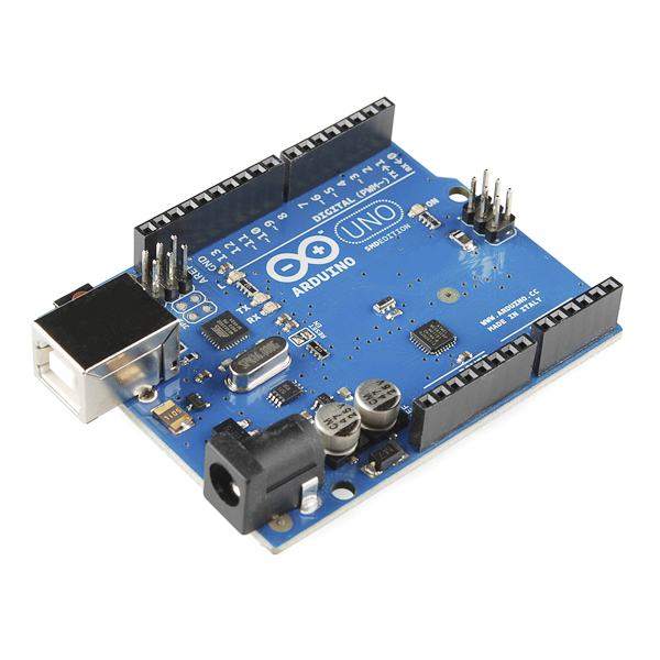
This is where Arduino comes into play. Arduino is a platform that is based on one microcontroller which is attached to a circuit board. Its convenient handling and easy programming, the lots of available hardware and the great community support make it one of the most popular prototyping platforms these days, especially for multidisciplinary applications. Among its many fans it already enjoys cult status. We first used the Arduino Uno. It is the most commonly used board. The first revision was released in September 2010. Designed for beginners, it gave us an easy start into the handling, since none of us had any experience working with microcontrollers. Most libraries already worked out of the box and all shields and sensors we ordered came with an example code. But the Arduino Uno came to it's limits, when we tried to get a display, WiFi and several sensors working.
Therefore we ordered the Arduino Due, which is the most powerful Arduino board at the moment. It has 16 times more flash memory (code storage) than the Arduino Uno and its clock runs 5 times faster. Instead of 2KB SRAM there are 96KB. At least there are a lot more free pins that can be used for sensors etc, and still its costs don't exceed 50€ (~60$).
| Component | Quantity | Source | Price | Figure |
|---|---|---|---|---|
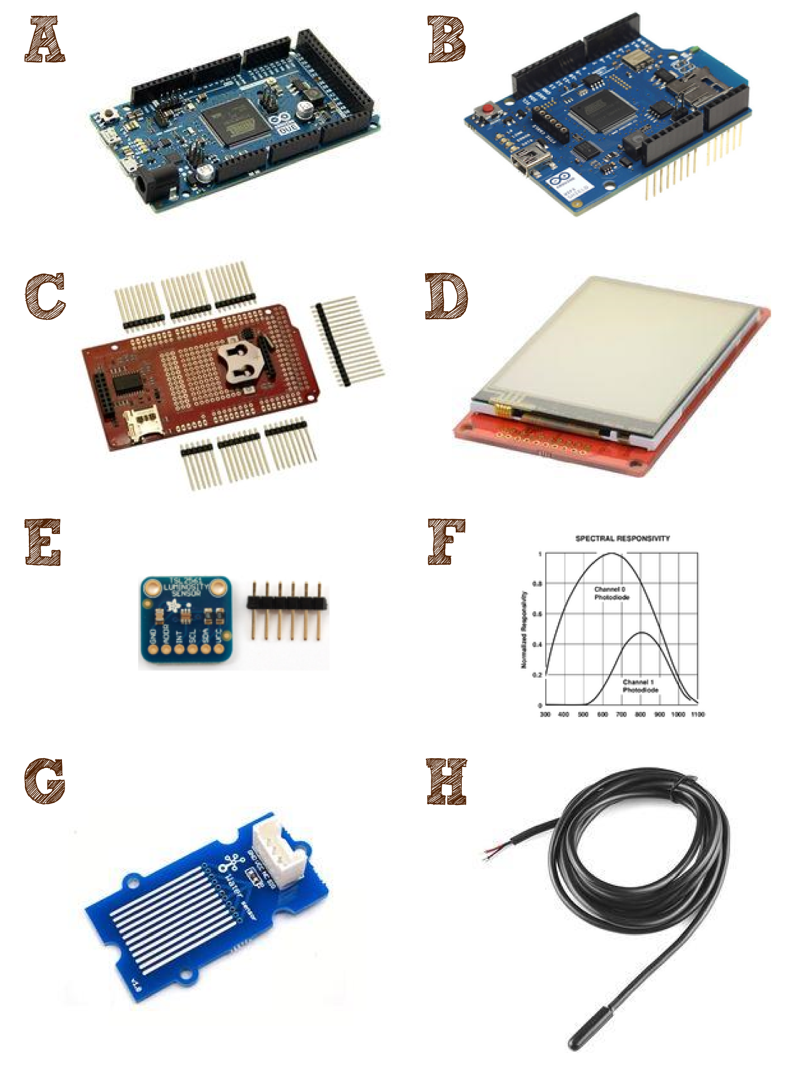
| Arduino Due microcontroller | 1 | Source | 46.41 € | Fig. 1 A |
| Arduino WIFI Shield | 1 | Source | 63.58 € | Fig. 1 B |
| Watterott mega msd-shield | 1 | Source | 19.49 € | Fig. 1 C |
| Display MI0283QT-9 | 1 | Source | 36.00 € | Fig. 1 D |
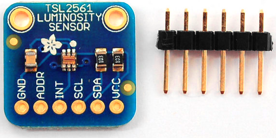
| Light sensor TSL2561 | 1 | Source | 7.74 € | Fig. 1 E |
| Temperature sensor DS18B20 | 1 | Source | 8.80 € | Fig. 1 F |
| Water sensor | 1 | Source | 2.90 € | Fig. 1 G |
| Lithium-Battery | 1 | Source | 16.35 € | |
| Stackable Headers | 3 | Source | 5.37 € | |
| Linking wires and resistors | 1.00 € | |||
| Photo-diodes | 3 | |||
| 207.64 € |
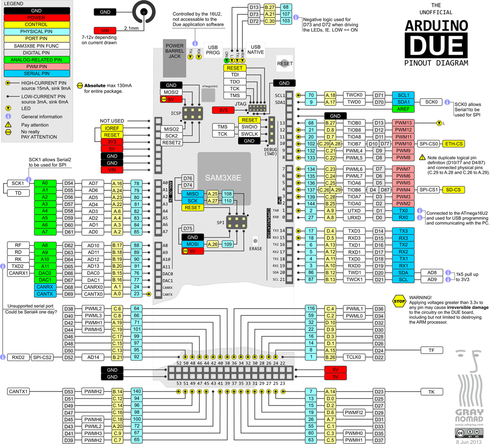
part description
Arduino Due
The Arduino Due is the most powerful Arduino board. It's underlying 32bit-processor is the Atmel SAM3X8E. Contrary to the other boards which run at 5V, a power supply of 3.3V is sufficiant.
Data:
 84 Mhz	CPU Clock
 96 	KBytes of SRAM.
512 	KBytes of Flash memory.
 54 	Digital I/O Pins
 12 	Analog Input Pins
  2 	(DAC)Analog Outputs Pins
Arduino WiFi Shield
The Arduino WiFi Shield is an attachable shield that provides Wireless LAN 802.11b/g to the Arduino. It scans and connects to networks and opens TCP and UDP sockets for data transfer. It also supports WEP and WPA2 encryption. The WiFi Shield is fully supported by the Arduino Due and Arduino supplies a suitable stock WiFi-library. There is also an on-board SD-card socket to store received data. As the SD-card is accessible separately, it can also be used as a storage for any data generated by the Arduino. The SD-card socket is also supported by a stock library. The communication between Arduino Due and the WiFi Shield runs via an SPI/ICSP interface.
Pin usage:
Pin  4	SS for SD card (Slave Select)
Pin  7	Handshake between Arduino and WiFi Shield
Pin 10	SS for WiFi
Pin 74	SPI MISO (Master in, Slave out)
Pin 75	SPI MOSI (Master out, Slave in)
Pin 76	SPI SCK  (Serial clock)
    gnd
    3.3V
    5V
Watterott mega msd-shield
The mega msd-shield was designed by Watterott and consists of a couple of components. The components are one real time clock, one SD-card socket (we won't use), a small battery and a socket for a touch display. To get it ready to run, the shield must be assembled. The stackable headers and the quartz must be soldered to the board and the battery must be inserted. Unluckily the mega msd-shield and therefore also the MI0283QT-9 touch display don't come with a working library for the Arduino Due. The existing library only supports all boards up to the Arduino Uno. Therefore all libraries have to be rewritten. The touch display and the SD-card-slot communicate with the Arduino Due via SPI/ICSP. The real time clock transmit its data via I²C.
Pin usage:
Pin  4	SS for SD card
Pin  6	SS for the touch of the touch display
Pin  7 (25)SS for the LCD (Workarround of the double usage of pin 7 by the WIFI Shield)
Pin  8	reset LCD
Pin  9	LCD LED
Pin 20	RTC (real time clock) 	I²C	SDA (Serial Data Line)
Pin 21	RTC  			I²C	SCL (Serial Clock)
Pin 50	SPI MISO
Pin 51	SPI MOSI
Pin 52	SPI SCK
    gnd
    3.3V
Display MI0283QT-9
The MI0283QT-9 is a multicolor touch display. It comes already attached to a board, where only the pin headers are left to be soldered. Once assembled it can easily be plugged into the mega msd-shield. It has an on-board touch controller (TI ADS7846). The display size is 2.83"(43.2 x 57.6mm) with a resolution of 240x320. It supports 262k colors. The pin usage is already considered in the mega msd-shield description.
Light sensor TSL2561
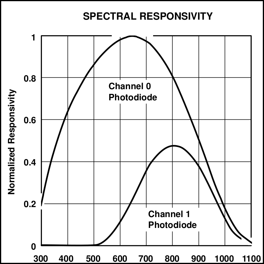
The light sensor is a small, so called, breakout board. It is usually connected by wires instead of directly plugged to the Arduino. The light sensor has two photo-diodes on-board that measure visible and infrared light. Similar to the RTC, the TSL2561 is addressed via I²C. Once you get the I²C library working on your Arduino Due working it takes only little effort to integrate additional I²C devices. Just very few lines of the library have to be rewritten here. The photo-diodes can be addressed separately or both at one. Their output is already converted to Lux.
pin usage:
Pin 20	TSL2561		 	I²C	SDA (Serial Data Line)
Pin 21	TSL2561			I²C	SCL (Serial Clock)
    gnd
    3.3V
Temperature sensor DS18B20
The temperature sensor is embedded into a water proof cable. It is addressed via a One-Wire interface. The provided data are digital raw data, which need to be converted into degrees Celsius. Information about the conversion are given by the manufacturer. Similar to the I²C (TwoWire) bus, you only have to get the One-Wire interface working once. After that, you can easily set up One-Wire more devices. Again, just very few lines of the library have to be rewritten.
pin usage:
Pin 14 	One-Wire DS18B20 (pin was randomly chosen)
Pin gnd
Pin 3.3V
Water sensor
Setting up the water sensor is very easy. If and how much water the sensor registered can be measured via an analog pin.
pin usage:
Pin A7	Water sensor
    gnd
    3.3V
Photo-diodes
We disassembled a broken "Biorad 550"-photometer and recovered a halogen lamp, a small number of wavelength filters, three of eight photo-diodes and their fitting Resistors.
Tools
- Breadboard
- Soldering bolt
- Solder
Assembly
Keep everything clear during your assembly. If you have different colored linking cables, always try to use the same color code. For example: brown cable for 3.3V etc. Troubleshooting can get nasty.
How could it look installed in a river?
NY parallel networks
In the Desing competition for NYC of the year 2011 we found an impressive proposal how a river could be used to meed all the requirements of an urban population by insalling swimming triangles. The winning contribution for the ONE PRIZE: Water as the 6th Borough was designed by the canadians Ali Fard and Ghazal Jafari which was called File:TUM13 NY PARALLEL NETWORKS.PDF NY pralllel networks. These triangles, so called pods fulfill different tasks such as the fixation of carbon dioxide, food production and local recreation without hindering the renewable energy generation and transporatation of passengers and goods. We believe that this design could become realized and that an additional sort of swimming pod with a PhyscoFilter could complete this desing.
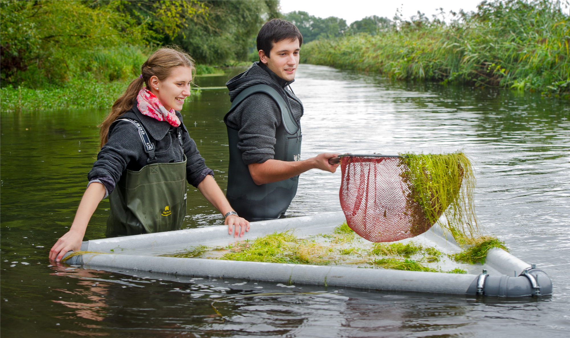
The Pods utelized in this proposal
Commercially availible pods called "Kampen"
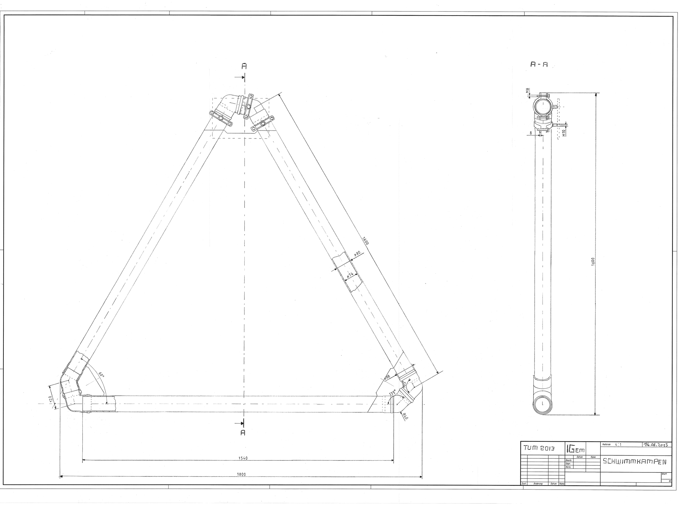
In the search for a possibility to built swimming pods for our moss filter we found BGS Ingenieurbiologie und -ökologie GmbH which is a German company which developed and provids solutions for the revegeation of rivers and wetlands.
Our own swimming pod for the implementation of our PhyscoFilter
Swimming PhyscoFilter Pod in action
References:
- [Edens et al., 1984] Edens, L., Bom, I., Ledeboer, A. M., Maat, J., Toonen, M. Y., Visser, C., and Verrips, C. T. (1984). Synthesis and processing of the plant protein thaumatin in yeast. Cell, 37(2):629–33.
 "
"










AutoAnnotator:
Follow us:
Address:
iGEM Team TU-Munich
Emil-Erlenmeyer-Forum 5
85354 Freising, Germany
Email: igem@wzw.tum.de
Phone: +49 8161 71-4351