 "
"
Team:TU-Delft/Timer Plus Sumo
From 2013.igem.org
Timer Plus Sumo
In this section the system of Figure 1 is modeled. The structure of the timer has two repressing promoters (PcI and Ptet) and the input is the T7 promoter and the output is the protease Ulp-1. This Ulp-1 cleaves off the SUMO from the produced SUMO+peptide.
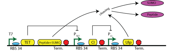
Figure 1: Circuit of the timer including sumo cleaving
By this model we are finding answers to the following questions:
- At what time point does the peptide+SUMO start to be produced?
- After how many minutes does the Ulp-1 cleave the peptide?
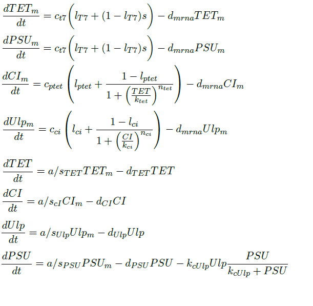
Differential Equations
The above circuit can be represented by the following differential equations. We assume a binary behavior of the T7 promoter. In the presence of IPTG, the T7 promoter will be active. So, we make the assumption that the T7 is binary variable with two possible states: either active 1 or inactive 0.
Parameters
For the stated parameters of the differential equations many values can be found in the literature. The degradation rates are relatively unknown, while the transcription rates vary widely. Many of these transcription rates resulted in our model in infeasible results, e.g. concentrations of millions of molecules per cell. For the PT7 a relative low transcription rate was thus selected in order to get the values in a reasonable range. The other promoters in the model we found as a fraction of the transcription rate of PT7 in the literature.
| Parameter | Value | Description | Units | Reference |
| ca | 1020 | Translation rate per amino acid | min-1#a-1 | [7] |
| cT7 | 4.16 | Maximum transcription rate of T7 | #m/min | [2] |
| cptet | 2.79 | Maximum transcription rate of Ptet | #m/min | [4] |
| cci | 1.79 | Maximum transcription rate of Pci | #m/min | [3] |
| dmRNA | 0.231 | Degradation rate of mRNA | min-1 | [8] |
| dTET | 0.1386 | Degradation rate of TET | min-1 | [9] |
| dCI | 0.042 | Degradation rate of CI | min-1 | [9] |
| dPEP | 2.1*10-3 | Degradation rate of the peptide | min-1 | Assumed three times slower same as GFP |
| dPSU | 6.3*10-3 | Degradation rate of the peptide plus SUMO | min-1 | Assumed the same as GFP |
| dUlp | 1.263*10-2 | Degradation rate of Ulp | min-1 | Assumed twice the rate of GFP |
| lt7 | 0.002 | Leakage factor of T7 | - | Assumption |
| lptet | 0.002 | Leakage factor of Ptet | - | Assumption |
| lci | 0.002 | Leakage factor of Pci | - | Assumption |
| ktet | 6 | Dissociation constant of Ptet | #m | [10] |
| kci | 20 | Dissociation constant of Pci | #m | [10] |
| kcUlp | 3 | Turnover rate of Ulp | min-1 | [6] |
| nci | 3 | Hills coefficient | - | [11] |
| ntet | 3 | Hills coefficient | - | [11] |
| s | 0 or 1 | Activation/Inactivation of T7 promoter | Binary | Assumption |
| sci | 228 | Length of CI | amino acids | [12] |
| sPSU | 18 + 110 | Length of peptide plus SUMO | amino acids | [12] |
| sTET | 206 | Length of TET | amino acids | [13] |
| sUlp | 233 | Length of Ulp1 | amino acids | [13] |
Variables
| Variable | Description |
| TETm | concentration of translated TET |
| PSUm | concentration of translated peptide plus SUMO |
| CIm | concentration of translated Ci |
| Ulpm | concentration of translated Ulp |
| TET | concentration of transcribed TET |
| PSU | concentration of transcribed peptide plus SUMO |
| CI | concentration of transcribed Ci |
| Ulp | concentration of transcribed Ulp |
Results
Here the results are given of the simulation upon activating the T7 promoter. For starting conditions the steady state values of the concentrations are used when T7 is switched off.

Figure 2: Simulation Results
Conclusion/Discussion
In the graph of Figure 2 the behavior of the circuit can be seen and the answers to the questions can be given:
- The peptide+SUMO is being produced at time point zero, reaching the maximum number of molecules, 3400 molecules, at time point 70.
- The cleaving of the SUMO can be observed from the start probably due to the fact that the promoter is leaky. After 80 minutes more Ulp-1 is produced, leading to an increased cleaving of the SUMO.