Team:TU-Delft/Zephyr How
From 2013.igem.org
Jfkooijman (Talk | contribs) |
Jfkooijman (Talk | contribs) |
||
| Line 320: | Line 320: | ||
<div class="img"> | <div class="img"> | ||
| - | <a target="_blank" href="https://static.igem.org/mediawiki/2013/2/23/Building_3.jpg"><img src="https://static.igem.org/mediawiki/2013/2/23/Building_3.jpg" alt=" | + | <a target="_blank" href="https://static.igem.org/mediawiki/2013/2/23/Building_3.jpg"><img src="https://static.igem.org/mediawiki/2013/2/23/Building_3.jpg" alt="id3" height="420"></a> |
<div class="desc">Assembly of C</div> | <div class="desc">Assembly of C</div> | ||
</div> | </div> | ||
Latest revision as of 17:23, 4 October 2013

How? The Zephyr DIY guide
How to make the Zephyr can be broken down in different modules: first the buying of materials and parts, then the making of several parts, assembling them, wiring the electronic circuit, programming the microprocessor, controlling the set-up from the pc and calibrating the image stitching to make a complete image.
Part list
In Table 1 the parts are listed into three categories: optical-, electrical- and mechanical components with a possible online store to buy the components. The plastic PMMA sheets are difficult to acquire online, it usually works the best to contact a local plastic supplier. Most of the mechanical parts can be swapped out for ones with the same dimensions, e.g. the bearings.
Note that in this list only dichroic parts for GFP are listed, for other wavelengths other parts are necessary. The dichroic parts are the excitation- and emission filter and the dichroic mirror itself. For many fluorescent proteins Edmund Optics has listed a good choice for these. If your fluorescent protein is not on there, the following guidelines may help you: Find out the emission frequency of your protein, pick the frequency of the 25 mm emission filter as close as possible. Pick the dichroic 25.2 x 35.6mm mirror 20 nm lower than this frequency and the 25 mm excitation filter 40 nm lower than the emission filter.
In addition to these filters and the mirror, you will also need a high power LED. The emission frequency of this LED should be very close to the frequency of the emission filter. Many of these LEDs are available on superbrightleds.com.
| Product name | Explanation | Quantity | Link |
|---|---|---|---|
| Optical components | |||
| 520nm Bandpass Filter, 36nm Bandpass, OD6 Blocking, 25mm Dia, Stock No. #67-030 | Emission filter | 1 | link 1 |
| 472nm Bandpass Filter, 30nm Bandpass, OD6 Blocking, 25mm Dia, Stock No. #67-027 | Excitation filter | 1 | link 2 |
| 495nm Dichroic Filter, 25.2 x 35.6mm, Stock No. #67-079 | Dichroic mirror | 1 | link 3 |
| 4X DIN Plan Commercial Grade Objective, Stock No. #67-706 | Objective | 1 | link 4 |
| 10X DIN Wide Field Microscope Eyepiece, Stock No. #36-130 | Eyepiece | 1 | link 5 |
| Electronical components | |||
| 42mm steppermotors 1.8°, 1A, 0.27 Nm, Bestnr.: 198722 - 89 | Stepper motors | 4 | link 6 |
| Logitech C270 HD Webcam | Webcam | 1 | link 7 |
| Arduino UNO Rev3, Artikelnummer 17458449 | Arduino microprocessor | 1 | link 8 |
| EasyDriver Stepper Motor Driver | Drivers to power steppermotors | 2 | link 9 |
| DC adapter, 24 V 1.2A | Adapter to power steppermotors | 1 | link 10 |
| XPE series Cree LED blue | High power LED | 1 | link 11 |
| USB-kabel A/B 1.80m | USB cable to connect with pc | 1 | link 12 |
| Resistor 5W 5,6Ohm | Resistor for the LED | 1 | link 13 |
| Electrical wire | Electrical wire to connect parts | - | |
| Mechanical parts | |||
| PMMA clear 6mm thick, 870 mm x 540 mm | The plastic for the frame | 1 | - |
| PMMA clear 6mm thick, 515 mm x 290 mm | The plastic for the frame | 1 | - |
| PMMA clear 3mm thick, 300 mm x 150 mm | The plastic for the frame | 1 | - |
| Linear bearring 15 mm 8 mm 24 mm | Bearrings allowing sliding | 8 | link 15 |
| Pouley 30 tooths, 6 mm diameter hole | Pouley to move the belt | 8 | link 16 |
| Belt 950 mm, 380 tooths | Drive belt | 4 | link 17 |
| Axis 8MM diameter 312 mm length | C19 | 4 | link 18 |
| Axis 8MM diameter 335 mm length | C20 | 2 | link 19 |
| Bearring inside diameter 6 mm outer diameter 19 mm | Bearrings to hold pouleys | 4 | link 20 |
| Fixation rings 8 mm | To fixate the axis | 12 | link 21 |
| SM1V10 - Ø1" SM1 Lens Tube, 1" Long External Threads | Lens tube allowing focussing | 1 | link 22 |
| CP4S - SM1-Threaded 30 mm Cage Plate, 4 mm Thick | Plate mounting for the lens | 1 | link 23 |
| SM1A3 - Adapter with External SM1 Threads and Internal RMS Threads | Adapter between different threads | 1 | link 24 |
| M6 bolts x 40 mm +nuts | 4 to support the pouleys and 4 for the holding of the objectie plate | 8 | - |
| M3 bolts x 20 mm + nuts | To tightent belts to sliders | 8 | - |
| Black paint | e.g. exhaust paint | 1 | - |
| Heat transfer double sided tape | To fixate the high power LED | 1 | link 25 |
| M3 bolts x 15 mm | To mount motors | 16 | |
| Glue | To fixate webcam | - |
Table 1: The parts to buy of the Zephyr, including dichroic parts for GFP detection.
Making of the parts
In total 41 unique parts must be made out of plastic using laser cutting. These parts are dived into four categories: A to D. A are the parts of the dichroic holder including the LED holder. B are the parts of the optical holder, C are the frame parts and D are the parts that hold petridishes and the 96 well plates. In the table below the parts are listed with their name and their coding (e.g. B3).

For all these parts technical drawings are available below or bundled in this pdf. Note that these are the dimensions that result from using the laser cutting method.

Figure 1: The Individual technical drawings of the parts to make
So, how to make these parts? For laser cutting the parts to make must usually be supplied a ‘dxf’-format, this is a file containing the 2D structure of the different parts. For all the different parts these files can be found in this zip-file. These digital files can be directly sent to a company that can make them for you or a technician at a university. The three plastic plates will suffice to make all the parts according to the quantity. You will have to ask them to combine them in a smart way for you on the plate. This would look something in Figure 2.

Figure 2: Example of the collection of the different parts in the laser program

Figure 3: Example of the parts being lasered out a PMMA plate
After these parts are cut, all the A and B parts must be painted. Paint both of the sides like in Figure 4, this will prevent reflection of light inside the optical tube and interference of outside light.

Figure 4: Example of painting the A- parts.
Assembly of the parts
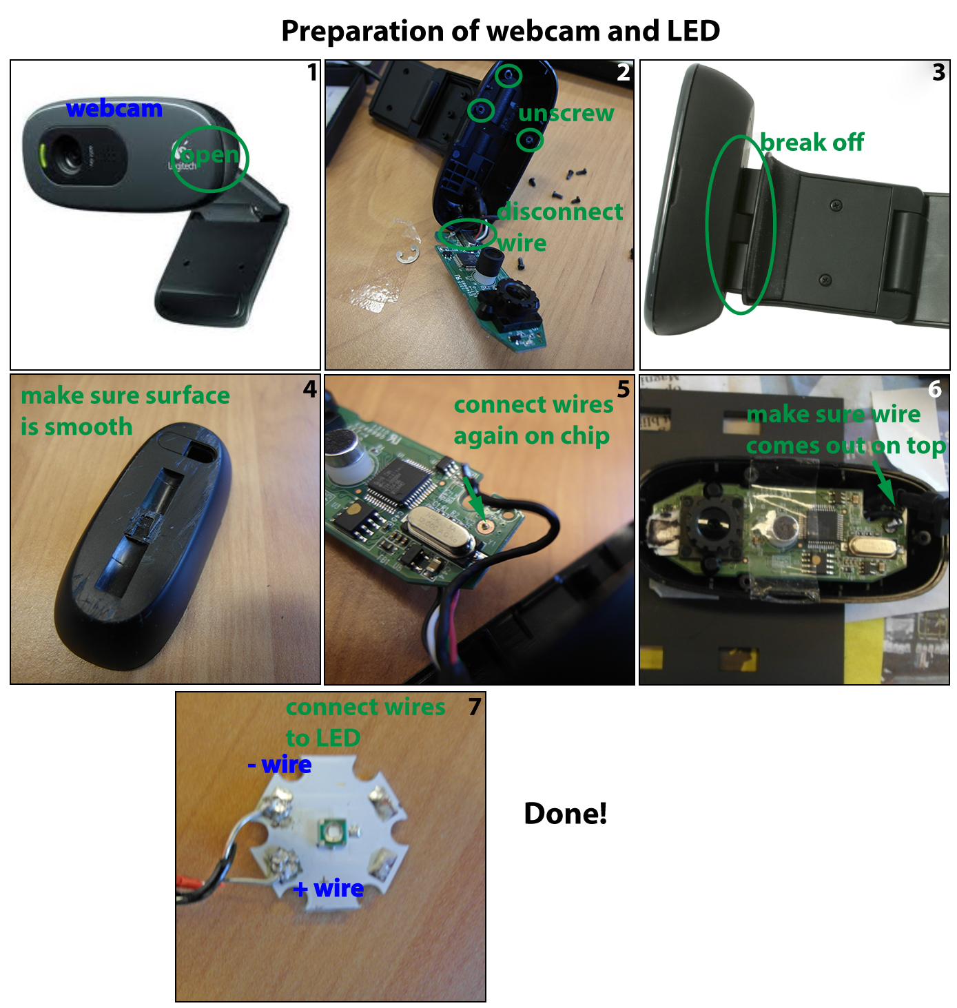
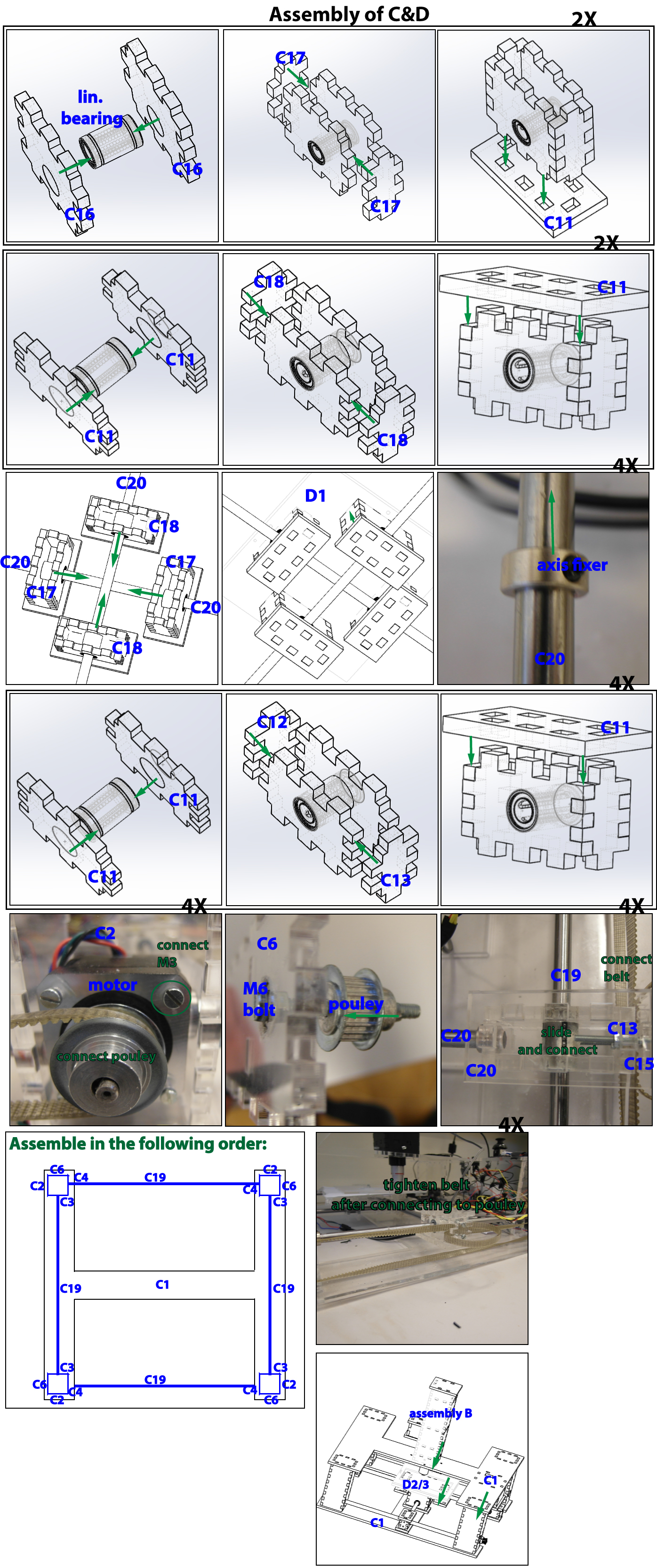
The assembly is described in the images below in a step-wise manner. Before starting, the webcam must be modified and the LED wired, see the file on preparation. After this it is sequentially assembling A, B and C.
Wiring the circuits
Now that everything is assembled, the electrical circuit must be made. It consists of 4 major components: the Arduino, the motor drivers, the motors and the LED. The LED is connected in series with a resistor to the Arduino, and the motors via the drivers to the Arduino. The total schematic is shown in Figure 6. Note that the motors in one direction are connected in series, since the motion must be the same for these two motors. For example if you want to move the table along the x-axis two motors should move: one pulling the drive belt and one pushing the drive belt. The wiring colors of stepper motors are not uniform, so you will have to do some trial and error to get this working correctly.

Software
The Arduino controls both the LED, all the motors and communicates with the PC. Attached is the zip file containing all the software, including the Arduino code file. This file can be uploaded to the Arduino using the Arduino software. It starts the scanning at the command of the PC and sends the time instances the photo must be taken. On the pc, the control software is written in Visual C++. Upon starting it opens a command window in which the scanning can be started and through which the webcam images are saved in a folder on the hard drive.
The image processing is done in Matlab in two steps. Our experience shows that the displacements between the pictures are unfortunately not constant. To deal with this we designed stitching software that finds the ROI of pictures and the displacements between pictures and then pastes them together, see for an example Figure 7. The two steps are first a calibration using a text and then the actual scanning using the fluorescent filters. This calibration text is a text with a small font (e.g. 2pt) which allows the stitching program to have enough features to find the correct displacements between the pictures. This scanning is done without the dichroic module (subassembly A) present. An example of this text is in Figure 8, a 5 eurocent coin is added for reference. Once the pattern of displacements is found, the Zephyr can scan the petridish on fluorescence and stitch the images together using this found pattern.


 "
"


