Team:Calgary/Project/OurSensor/Prototype
From 2013.igem.org
TRemondini (Talk | contribs) |
|||
| (9 intermediate revisions not shown) | |||
| Line 9: | Line 9: | ||
<h2>Initial Ideas</h2> | <h2>Initial Ideas</h2> | ||
| - | </html>[[File:UC_2013_PregTests.jpg| | + | </html>[[File:UC_2013_PregTests.jpg|250px|right]]<html> |
| - | <p>When we started thinking about how to turn our project into a product that could be readily used by the beef industry we wanted a portable and easy to use device. Initial discussions with industry also pointed out that speed was important | + | <p>When we started thinking about how to turn our project into a product that could be readily used by the beef industry, we wanted a portable and easy to use device. Initial discussions with industry also pointed out that speed was important. If it took 24 hours to get the result then the infected cow would have already been processed and thereby the entire batch contaminated. To get inspiration, we went for a walk around our local pharmacy to see what kind of sensors we could buy and explore. As we were walking through the aisles we saw digital and colour change thermometers, pressure based heart rate monitors, blood glucose meters, and pregnancy tests. While the idea of having a digital output was initially interesting to us, we soon realized that the home pregnancy test was one of the easiest and well known sensors with an output that can be understood by anyone. Another bonus was that the designs have already been optimized to use biological molecules as the recognition elements, just like we were planning to do.</p> |
| - | <p>With that in mind we sent two of our male advisors (Robert & Iain) to pick out their favourite pregnancy tests. The fruits of their labour can be seen to the right | + | <p>With that in mind we sent two of our male advisors (Robert & Iain) to pick out their favourite pregnancy tests. The fruits of their labour can be seen to the right (they even got two different kinds!).</p> |
<h2>Making the prototype from the pregnancy test</h2> | <h2>Making the prototype from the pregnancy test</h2> | ||
| - | <p>We disassembled the tests to see the inner workings of the test. The components can be seen below | + | <p>We disassembled the tests to see the inner workings of the test. The components can be seen below. </p> |
| - | </html>[[File:UC2013_PregTestInsides.jpg| | + | </html>[[File:UC2013_PregTestInsides.jpg|400px]]<html> |
<p>There were more components than we had expected, with an applicator, transfer wick, nitrocellulose, dragging wick, and a dessicator stone at the end. Through playing with the components we found that the dragging wick (after the nitrocellulose to pull the liquid sample as far as possible) was not completely necessary, but did seem to aid in covering the nitrocellulose. We believe the dessicator is for long term storage of the device, as it played no discernable role in our bench testing.</p> | <p>There were more components than we had expected, with an applicator, transfer wick, nitrocellulose, dragging wick, and a dessicator stone at the end. Through playing with the components we found that the dragging wick (after the nitrocellulose to pull the liquid sample as far as possible) was not completely necessary, but did seem to aid in covering the nitrocellulose. We believe the dessicator is for long term storage of the device, as it played no discernable role in our bench testing.</p> | ||
| Line 25: | Line 25: | ||
<p>To test if our system of using ferritin would give us a readable output from a prototype we blotted prussian blue ferritin onto nitrocellulose. We then enclosed the blotted nitrocellulose in one of the pregnancy tests along with the applicator and wicks that came with it before exposing it to the TMB substrate. Unfortunately we didn't see any change after our first test, but after taking it apart to look inside we found that the solution had only flowed through approximately one third of the device. With that in mind we built our second prototype out of another pregnancy test, but this time we shortened the distace by cutting part of the applicator off. The downside of this modification was that the applicator was rendered useless, so filter paper was used to draw the solution into the device instead. In this prototype, shown below, we were able to observe a change in prussian blue ferritin after the addition of the substrate TMB.</p> | <p>To test if our system of using ferritin would give us a readable output from a prototype we blotted prussian blue ferritin onto nitrocellulose. We then enclosed the blotted nitrocellulose in one of the pregnancy tests along with the applicator and wicks that came with it before exposing it to the TMB substrate. Unfortunately we didn't see any change after our first test, but after taking it apart to look inside we found that the solution had only flowed through approximately one third of the device. With that in mind we built our second prototype out of another pregnancy test, but this time we shortened the distace by cutting part of the applicator off. The downside of this modification was that the applicator was rendered useless, so filter paper was used to draw the solution into the device instead. In this prototype, shown below, we were able to observe a change in prussian blue ferritin after the addition of the substrate TMB.</p> | ||
| - | </html>[[File:UC2013_Prototype2.jpg| | + | </html>[[File:UC2013_Prototype2.jpg|400px]]<html> |
<h2>Sample Preparation</h2> | <h2>Sample Preparation</h2> | ||
| - | </html>[[File:UC_2_0_1_3_Electrodes.JPG| | + | </html>[[File:UC_2_0_1_3_Electrodes.JPG|250px|right]]<html> |
<p>In order for our test to work we need the DNA to be accessible for our TALEs. Unfortunately, bacteria keep their DNA contained inside their membranes, meaning that we need to lyse the cells in order for our test to work. Most methods that lyse cells either take upwards of 10 minutes, needs human intervention, or involves the use of larger equipment than the industry wants to use (i.e: requiring an electrical outlet). With that in mind we scoured the literature for an alternate method and discovered a paper where the authors lysed bacteria with a brief exposure to electricity (Besant <i>et al.</i>, 2013). With that in mind we designed our rudimentary lysis device, shown to the right, that used the electrodes from a broken elecrophoresis setup to electrocute a sample.</p> | <p>In order for our test to work we need the DNA to be accessible for our TALEs. Unfortunately, bacteria keep their DNA contained inside their membranes, meaning that we need to lyse the cells in order for our test to work. Most methods that lyse cells either take upwards of 10 minutes, needs human intervention, or involves the use of larger equipment than the industry wants to use (i.e: requiring an electrical outlet). With that in mind we scoured the literature for an alternate method and discovered a paper where the authors lysed bacteria with a brief exposure to electricity (Besant <i>et al.</i>, 2013). With that in mind we designed our rudimentary lysis device, shown to the right, that used the electrodes from a broken elecrophoresis setup to electrocute a sample.</p> | ||
| Line 35: | Line 35: | ||
<p>To test the lysis capabilities of this device we took 50 µL of an overnight RFP culture and exposed it to 0, 10, 20, 30, or 40 V of electricity from a power pack for 5 seconds. We then plated the electrocuted samples to see if they were capable of growing, but even before the results came in there was a marked change in the appearance of the sample, changing from red and cloudy to clear and yellow. When the cells were grown and exposed to UV light for easy visibility it was noted that only the 0 V and 10 V samples grew, with the 20, 30, and 40 V treatments killing all cells.</p> | <p>To test the lysis capabilities of this device we took 50 µL of an overnight RFP culture and exposed it to 0, 10, 20, 30, or 40 V of electricity from a power pack for 5 seconds. We then plated the electrocuted samples to see if they were capable of growing, but even before the results came in there was a marked change in the appearance of the sample, changing from red and cloudy to clear and yellow. When the cells were grown and exposed to UV light for easy visibility it was noted that only the 0 V and 10 V samples grew, with the 20, 30, and 40 V treatments killing all cells.</p> | ||
| - | </html>[[File:Calgary_2013_Volts.jpg| | + | </html>[[File:Calgary_2013_Volts.jpg|600px]]<html> |
<h2>Final System Testing</h2> | <h2>Final System Testing</h2> | ||
| - | <p>We are currently in the final stages of testing our prototype system | + | <p>We are currently in the final stages of testing our prototype system. Tests over the next few weeks will determine if we can capture DNA from lysed cells on our bound TALEs and then get a response from our ferritin molecule. A video describing the whole system that we plan on testing can be found <a href="http://www.youtube.com/watch?v=dAO0mCi8vFU">here</a>.</p> |
</section> | </section> | ||
</html> | </html> | ||
Latest revision as of 03:55, 29 October 2013
Prototype
Prototype
Initial Ideas
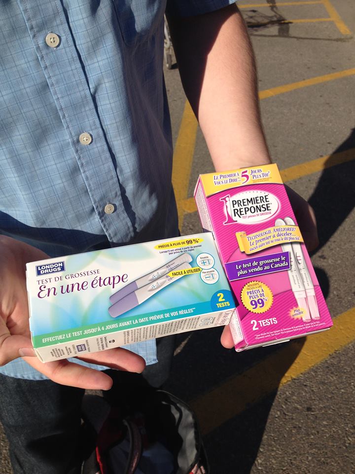
When we started thinking about how to turn our project into a product that could be readily used by the beef industry, we wanted a portable and easy to use device. Initial discussions with industry also pointed out that speed was important. If it took 24 hours to get the result then the infected cow would have already been processed and thereby the entire batch contaminated. To get inspiration, we went for a walk around our local pharmacy to see what kind of sensors we could buy and explore. As we were walking through the aisles we saw digital and colour change thermometers, pressure based heart rate monitors, blood glucose meters, and pregnancy tests. While the idea of having a digital output was initially interesting to us, we soon realized that the home pregnancy test was one of the easiest and well known sensors with an output that can be understood by anyone. Another bonus was that the designs have already been optimized to use biological molecules as the recognition elements, just like we were planning to do.
With that in mind we sent two of our male advisors (Robert & Iain) to pick out their favourite pregnancy tests. The fruits of their labour can be seen to the right (they even got two different kinds!).
Making the prototype from the pregnancy test
We disassembled the tests to see the inner workings of the test. The components can be seen below.
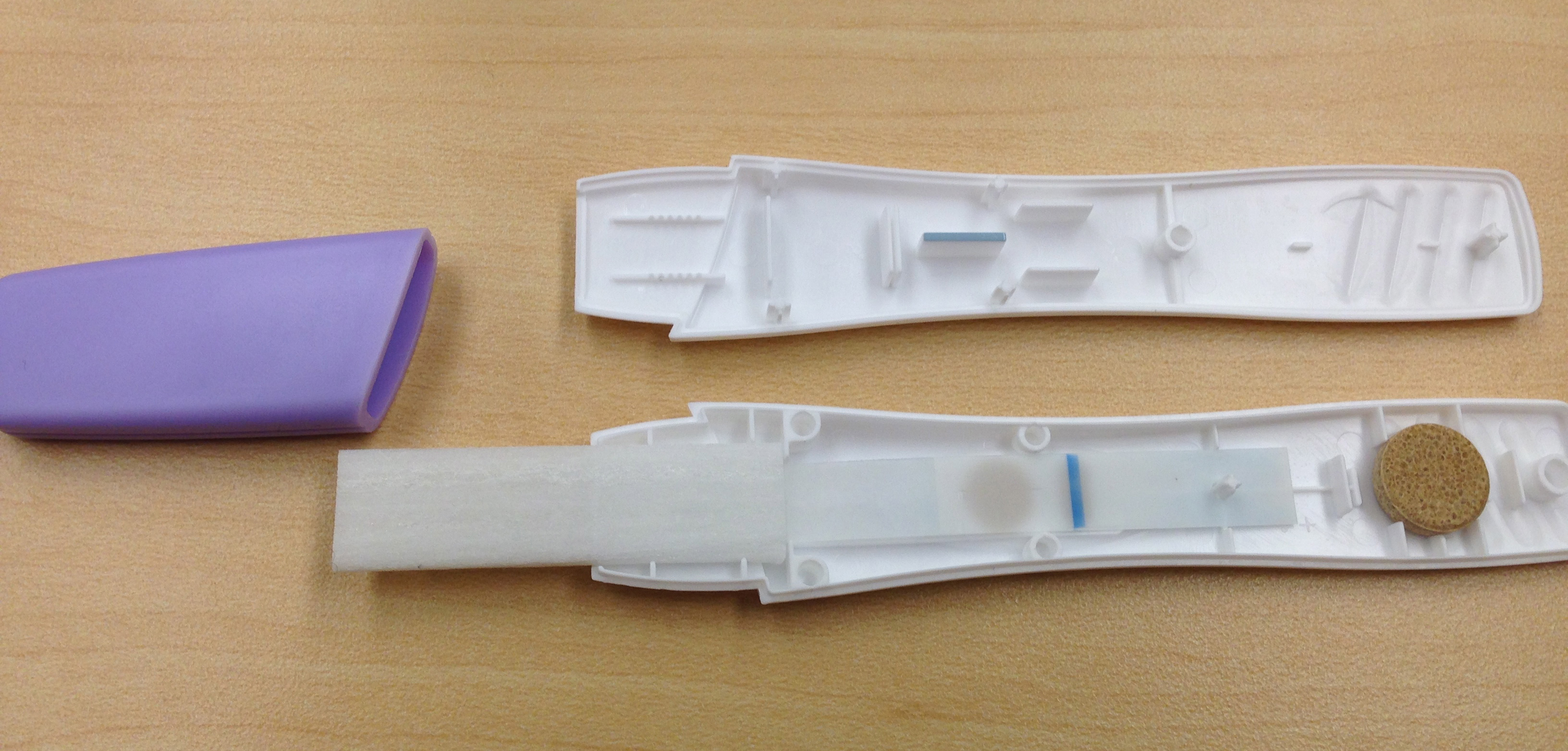
There were more components than we had expected, with an applicator, transfer wick, nitrocellulose, dragging wick, and a dessicator stone at the end. Through playing with the components we found that the dragging wick (after the nitrocellulose to pull the liquid sample as far as possible) was not completely necessary, but did seem to aid in covering the nitrocellulose. We believe the dessicator is for long term storage of the device, as it played no discernable role in our bench testing.
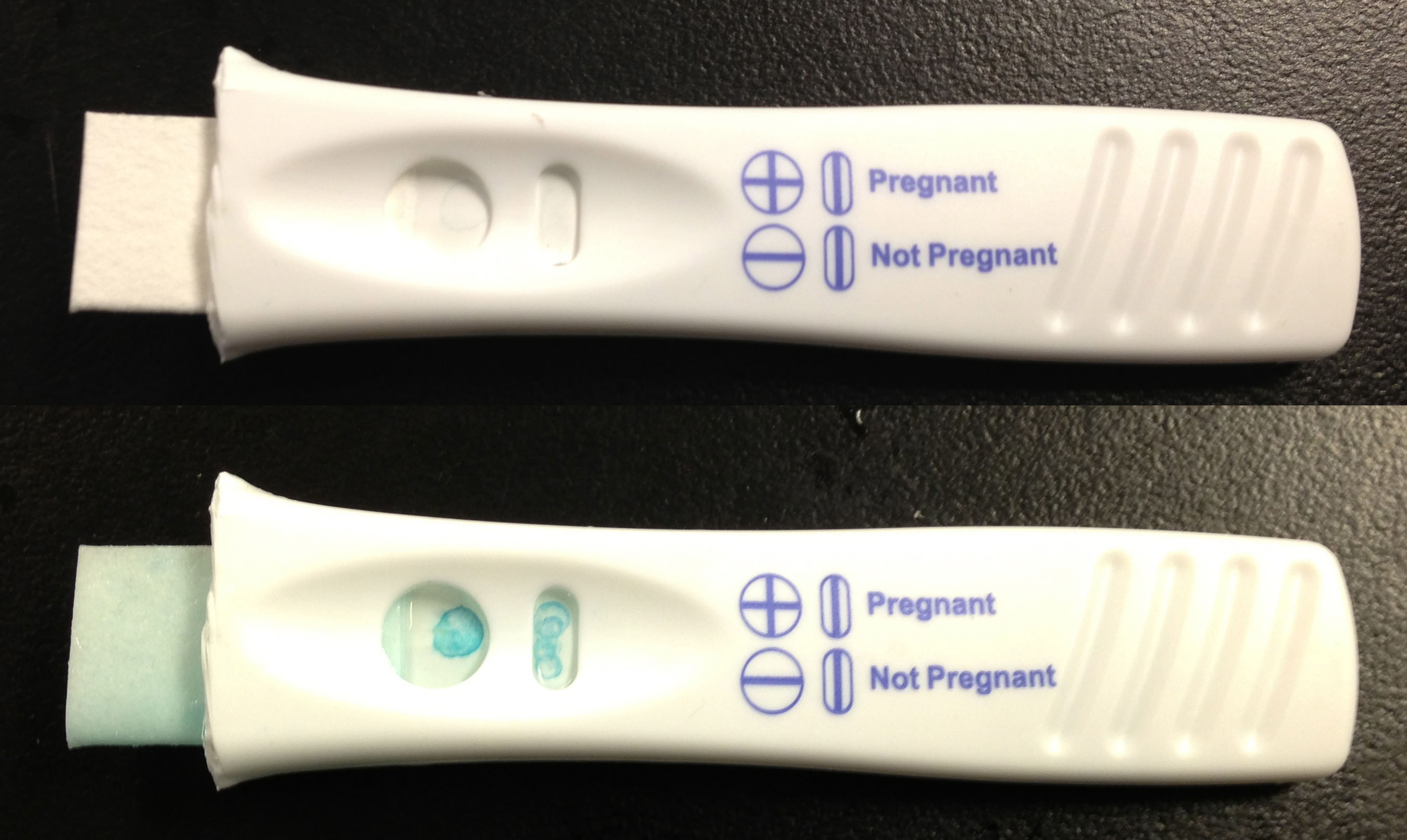
To test if our system of using ferritin would give us a readable output from a prototype we blotted prussian blue ferritin onto nitrocellulose. We then enclosed the blotted nitrocellulose in one of the pregnancy tests along with the applicator and wicks that came with it before exposing it to the TMB substrate. Unfortunately we didn't see any change after our first test, but after taking it apart to look inside we found that the solution had only flowed through approximately one third of the device. With that in mind we built our second prototype out of another pregnancy test, but this time we shortened the distace by cutting part of the applicator off. The downside of this modification was that the applicator was rendered useless, so filter paper was used to draw the solution into the device instead. In this prototype, shown below, we were able to observe a change in prussian blue ferritin after the addition of the substrate TMB.
Sample Preparation
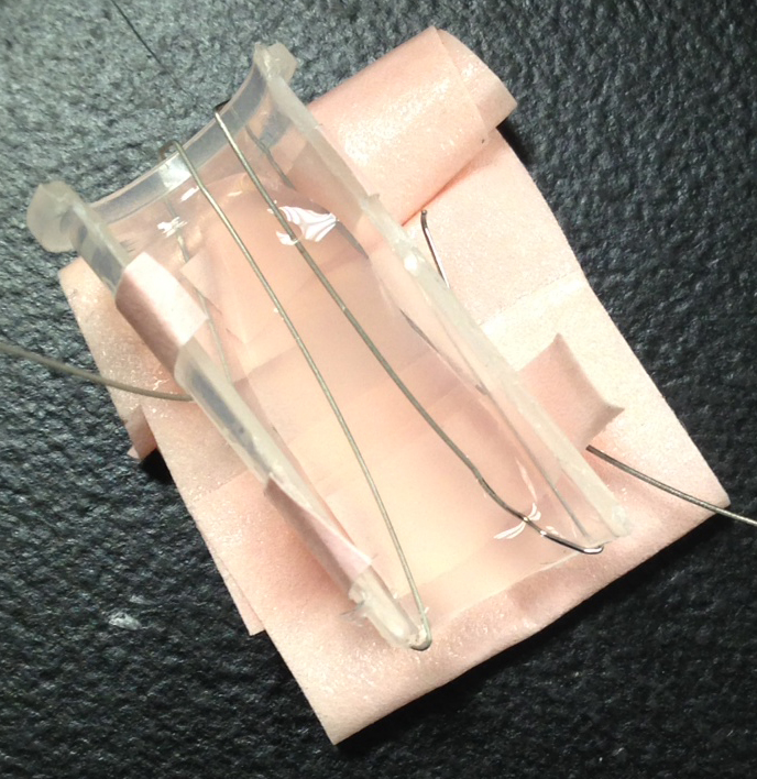
In order for our test to work we need the DNA to be accessible for our TALEs. Unfortunately, bacteria keep their DNA contained inside their membranes, meaning that we need to lyse the cells in order for our test to work. Most methods that lyse cells either take upwards of 10 minutes, needs human intervention, or involves the use of larger equipment than the industry wants to use (i.e: requiring an electrical outlet). With that in mind we scoured the literature for an alternate method and discovered a paper where the authors lysed bacteria with a brief exposure to electricity (Besant et al., 2013). With that in mind we designed our rudimentary lysis device, shown to the right, that used the electrodes from a broken elecrophoresis setup to electrocute a sample.
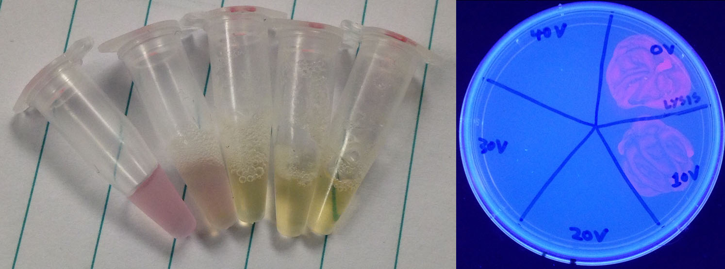
To test the lysis capabilities of this device we took 50 µL of an overnight RFP culture and exposed it to 0, 10, 20, 30, or 40 V of electricity from a power pack for 5 seconds. We then plated the electrocuted samples to see if they were capable of growing, but even before the results came in there was a marked change in the appearance of the sample, changing from red and cloudy to clear and yellow. When the cells were grown and exposed to UV light for easy visibility it was noted that only the 0 V and 10 V samples grew, with the 20, 30, and 40 V treatments killing all cells.
Final System Testing
We are currently in the final stages of testing our prototype system. Tests over the next few weeks will determine if we can capture DNA from lysed cells on our bound TALEs and then get a response from our ferritin molecule. A video describing the whole system that we plan on testing can be found here.
 "
"

