Team:Bielefeld-Germany/Project/MFC Efficiency
From 2013.igem.org
| Line 60: | Line 60: | ||
<html> | <html> | ||
<h1>MFC Efficiency</h1> | <h1>MFC Efficiency</h1> | ||
| - | <div id="buttonrow" style="padding-top:30px; padding-bottom:70px; padding-left: | + | <div id="buttonrow" style="padding-top:30px; padding-bottom:70px; padding-left:160px; clear:both;"> |
<div class="bigbutton"> | <div class="bigbutton"> | ||
<p><a href="https://2013.igem.org/Team:Bielefeld-Germany/Project/Abstract">Projects <br>Overview</a></p></div> | <p><a href="https://2013.igem.org/Team:Bielefeld-Germany/Project/Abstract">Projects <br>Overview</a></p></div> | ||
Revision as of 17:48, 27 October 2013
MFC Efficiency
Overview
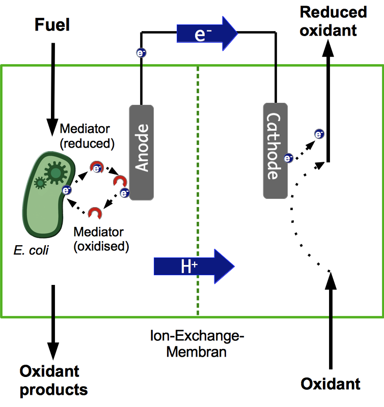
To determine how well the different BioBricks we create really work in the designated environment, the design and construction of a suitable microbial fuel cell was necessary. This fuel cell has to meet several requirements. As explained previously it should consist of two chambers, separated by a material that is only traversable for cations. Both chambers have to contain an electrode, which has to be electrically conductive. Also, they should have a large surface area, in order to allow contact to a high number of electron donors at the same time. Both the anode and the cathode chamber also have to be air-tight, since the reaction has to take place under anaerobic conditions. For obvious reasons, we aim at keeping the costs for the cell low by using materials which cost as little as possible while still performing well.
Construction of a first prototype began in May. After initial testing, the design underwent significant changes over the course of the project. Important stages of this process are shown below, along with a description of their design and the flaws that led to the planning of a new model.
Theory
General design
The general design of a microbial fuel cell is mainly influenced by the shape of the electrode chambers. A very simple design is called the “H” shape, which usually consists of two bottles or other vessels, connected by a tube containing a suitable separation material. Further investigations underlined the general usability of this system to test materials or parameters, but the power gain seems rather low. This is most likely the case because of the slow proton exchange through the tubes and because of a high internal resistance (Oh et al., 2004; Oh and Logan, 2006).
There are many other possible shapes, like a cylindrical reactor with a concentric inner tube that acts as the cathode to enable a continuous flow. One specific design, proposed by H. P. Bennetto (Bennetto, 1990), is often used for research purposes. The system consists of plastic elements in form of two solid plates and two frames, as shown in Figure 2. The frames are placed between the plates and form two reaction compartments, separated by a cation exchange membrane. Furthermore, every compartment is equipped with electrodes to enable a flow of electrons. To create a system with the option for anaerobic cultivation with simultaneous aeration and the possibility to add or remove liquid, the elements are fitted with ports. To ensure the system is air-tight, rubber gaskets are fitted between the plastic parts. The endplates are held together by four threaded rods.
- Requirements:
- formation of a closed system
- possibility for axenic cultivation
- possibility for anaerobic conditions
- large internal surface
Anode
In order to be used as an anode, a material has to be highly conductive, biocompatible and chemically stable under the conditions present inside the fuel cell. Many traditional materials like copper are not suitable, because of the highly toxic effect of heavy-metal ions to bacteria. Platinum works excellent, but is extremely expensive. Several carbon-based materials provide a cheap but practical alternative. Regarding this, the surface area is a very important factor for high current production. Previous investigations showed that current increases with the overall internal surface in the following order: carbon felt > carbon foam > graphite (Chaudhuri and Lovley, 2003).
- Requirements:
- high conductivity
- good biocompatibility
- long-term physical and chemical stability
Cathode
Because of its low overpotential in combination with carbon electrodes and the resulting working potential, which is close to its open circuit potential, potassium ferricyanide (K3)[Fe(CN) 6]) is the most frequently used electron acceptor in microbial fuel cells in research scenarios (Logan et al., 2006). However, one has to consider that the reoxidation by oxygen is very low and the diffusion through the PEM is not negligible, so that the oxidation of this substance can affect the performance of the MFC when operated for long periods of time (Rabaey et al., 2005). Alternatively oxygen can be used as a very effective electron acceptor in combination with an open-air electrode. For an effective oxygen reduction, however, high-cost platinum catalysts are necessary. For this reason, this option is rarely used (Sell et al., 1989).
- Requirements:
- good reduction performance
- good reoxidation
- high long term stability
Compartment separation
Although almost all microbial fuel cells use proton exchange membranes as the separation element between anode and cathode compartment, it is possible to use more simple constructions like salt or agarose bridges. These basic separation systems, however, do not reach the power output of membrane based systems because of the high internal resistance. Cation exchange membranes offer very defined properties and ensure a better current output because of their high selectivity for the passage of positive charged ions. However, in this context it has to be considered that the PEM could be permeable to chemicals and oxygen, which could influence the long term performance of the cell (Logan et al.,2006).
- Requirements:
- high selectivity for positive ions
- impermeability for chemicals and oxygen
MFC-Evolution
The Film Canister Cell
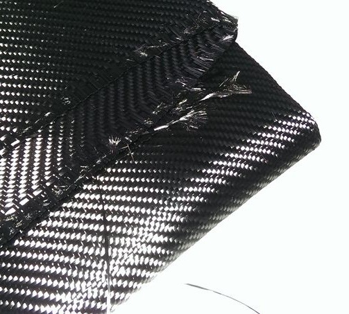
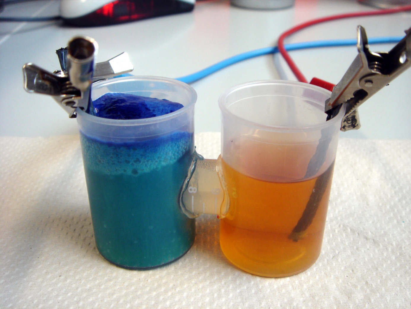
This is a model designed to gain better understanding about the general concept of galvanic cells and microbial fuel cells. It was used with different chemicals, yeast and the E. coli KRX strain. It also allowed to gather experience with the equipment used for measurement. The anode and cathode chambers are film canisters. Both have holes in their walls which are connected by roughly 2 cm long part of a 15 mL centrifugation tube. The individual parts are held together by hot-melt glue. The centrifugation tube is filled with 3 % agarose, which acts as a salt bridge to allow protons to pass from anode to cathode chamber. In both chambers, pieces of carbon tissue (see Figure 4) act as the electrode.
The biggest problem of this design is the salt bridge connecting both chambers. After being submerged in liquid for a while, it tends to become loose and glide out of the centrifugation tube. Furthermore, the construction does not allow for anaerobic operating of the fuel cell.
- Dimensions per Chamber:
- height: 50 mm
- diameter: 32 mm
- volume: 40.2 mL
The Film Canister Stack
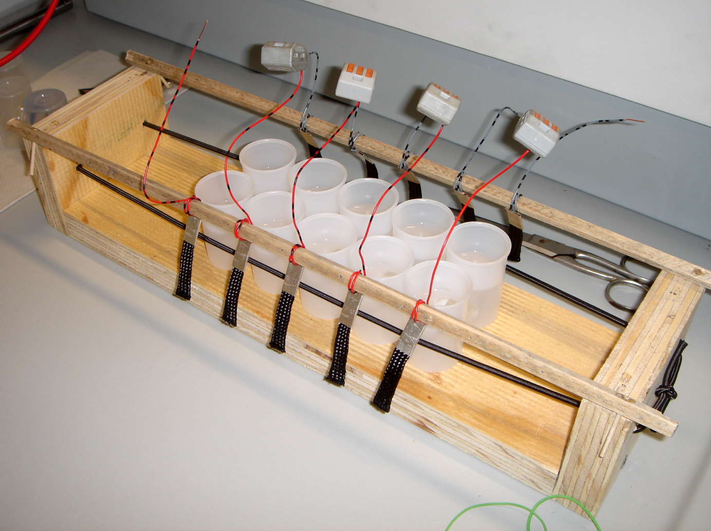
Connecting single batteries in series can be used to increase the output voltage. Likewise, the film canister stack consists of five film canister cells connected with copper wires in series. Because of the higher voltage generated, it was possible to operate a single low power light-emitting diode, using a high concentrated baker's yeast suspension and methylene blue in the anode chamber.
- Dimensions per chamber
(10 total):- height: 50 mm
- diameter: 32 mm
- volume: 201 mL total
The Second Generation Fuel Cell
This cell was designed with anaerobic operation in mind. The plastic parts needed were ordered from the workshop of the Faculty of Biology at Bielefeld University. The overall design is inspired by the fuel cell proposed by Benetto (Bennetto, 1990). Two frames make up the anode and cathode chamber. They are enclosed by two flat plates, which each have four bores. Threaded rods are put through the bores. The construction is held together by these rods, which have tightly fastened nuts on their ends.
All plastic parts are separated by thin rubber gaskets. A Nafion N117 membrane is placed between the two frames to allow cations to travel between the chambers. The two electrodes were initially cut out of the same carbon tissue as the ones used in the film canister cells. The rims were sown together with extra durable yarn to prevent the material from frazzling. These electrodes were held in place by two plastic pars plugged in each chamber. The copper wire connecting the electrode runs through two holes on the top of each plastic frame.
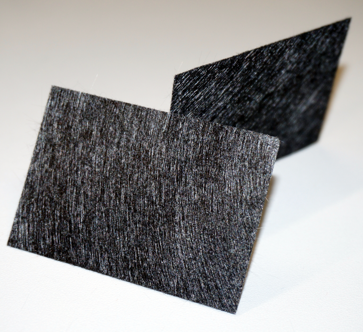
Initial testing revealed that the carbon cloth electrodes did not seem to be as conductive as expected. For this reason, they were replaced with electrodes made from another kind of carbon material, which were obtained from University of Readings [http://www.ncbe.reading.ac.uk/ National Centre for Biotechnology Education ]. However, the material is not very strong and easily ruptures, especially when wet. This made it difficult to connect the copper wires and to hold the electrodes in place within the chambers. The design also lacked means to drive out the oxygen from medium with nitrogen, an important prerequisite to establish anaerobic conditions within the fuel cell.
- Dimensions per chamber:
- height: 40mm
- width: 40mm
- depth: 14mm
- volume 22,4 mL
The Third Generation Fuel Cell
The fuel cell consists of six plastic parts. The overall design is similar to 2nd generation cell, but the frames are split up into two parts each. This allows for the carbon electrodes to be mounted between two frames, as was already the case for the membrane before. This ensures the fragile carbon cloth is fixed in the centre of each chamber and can be tapped by squeezing a wire between the gaskets. Since the material is extremely thin, bacteria and medium can diffuse through the electrode and travel between both halves of a single chamber.
The second important change from the previous design is the introduction of four tube connectors on each frame. This allows aeration of the anode chamber with nitrogen gas and, e.g., introducing fresh medium in the system. The copper wire connecting the electrodes is replaced with platinum, because of the rapid copper-oxidation, resulting in a decreased conductivity.
- Dimensions per chamber:
- height: 50mm
- width: 50mm
- depth: 12mm
- volume: 30 mL
The iGEM-York Cell
Since the iGEM Team York_UK is also doing work related to microbial fuel cells this year, we offered to send them one of our fuel cells to conduct their experiments in. Our design did not fully meet their requirements, especially since it was too large. After consulting with two of their team members, we build a small fuel cell based on the 3rd generation design and sent it to York.
- Dimensions per chamber:
- height: 25mm
- width: 25mm
- depth: 12 mm
- volume: 7,5 mL
The Stack
In order to increase the power output of the fuel cell, a fuel cell stack was built based on the third generation design. It consists of alternating anode and cathode chambers, five of each, placed between two cover plates. Using copper wiring, the five chamber-pairs are connected in series. Physically, they are separated by 1 mm thick stainless steel tiles, which act as bipolar plates.
- Dimensions per chamber
(10 total):- height: 50mm
- width: 50mm
- depth: 12mm
- volume: 150mL total
3D printing
To make the microbial fuel cell accessible to everyone, an additional model was developed which can be produced using a 3D printer. 3D printers are becoming more and more common and if none is available, the model can be ordered online from a 3D printing shop.
For our 3D printed microbial fuel cell it was important to apply material that does not inhibit microbial growth. To make sure this is the case, E. coli KRX was cultivated in the presence of two different kinds of plastic commonly used for 3D printing. These materials were acrylonitrile butadiene styrene (ABS) and polylactic acid (PLA), which are both thermoplastics that become moldable when heated and return to solid once the temperature drops.
A proper material for gaskets is essential as well, so different kinds of polysiloxane were tested in the same way. The rubber gaskets used in second and third generation MFC designs were also probed.
- Acrylonitrile butadiene styrene
- ABS as a polymer can take many forms and can be engineered to have many properties. In general, it is a strong plastic with mild flexibility (compared to PLA).
- It's strength, shapeability and higher temperature resistance make it often a preferred plastic by engineers and those with mechanical uses in mind.
- ABS can be smelted down and recycled very easily provided it is available in suitable purity. Sorting methods do exist to separate ABS from mixed wastes with high efficiency.
- Polylactic acid
- Created from processing any number of plant products including corn, potatoes or sugar-beets, PLA is considered a more 'environmental friendly' plastic compared to petroleum based ABS.
- When properly cooled, PLA seems to have higher maximum printing speeds, lower layer heights, and sharper printed corners.
- PLA is biodegradable, having a typical lifetime of about 6 months to 2 years until microorganisms break it down into water and carbon dioxide.
To assess the issue of possible growth retardation, we cultivated E. coli with each material and compared the measured growth curves to a control cultivation without added plastics.
The results shown in in figure LILA PAVIAN and figure UMBRA SEEPFERDCHEN demonstrate, that both ABS and PLA are biocompatible. Also, all brands of polysiloxane except B1 and the rubber are suitable as gasket material.
Models
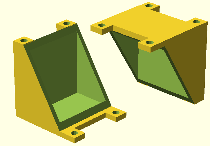
3D models were programmed with the software [http://www.openscad.org/ openSCAD], exported as .stl-files and translated into G-Code using [http://slic3r.org/ Slic3r].
Initially, slicing and printing took place at the local [http://hackerspace-bielefeld.de/ hackerspace] with counseling by experienced members of the groups. The printer, a [http://printrbot.com/ Printrbot Plus v2] was made available by the hackerspace community as well. After a total of roughly 34 hours of work, a first model was successfully printed from ABS. Like the models described in the MFC-Evolution paragraph, the design was changed several times. Some of the results can be seen in Figure 17. In early August, Bielefeld Universities Faculty of Physics offered their help. They printed out all subsequent designs with their [http://www.reprappro.com/products/mono-mendel/ RepRapPro Mono-Mendel] using PLA plastic and also executed the slicing process.
The final model, illustrated in Figure 19, was finished in September. It features a 4-part design like the second generation model described in the MFC-Evolution section and has tube connectors for aeration of each individual chamber. Polysiloxane is used instead of rubber gaskets, the membrane and electrodes are fixed between the four frames of the reaction chambers. The end plates are held together by M3 threaded rods with M3 nuts. The materials necessary for building this fuel cells chassis cost less than 4€ an the cell is biodegradable. The .stl-file is available for download here.
References
- Bennetto, H. P. (1990). Electricity generation by microorganisms. [http://www.ncbe.reading.ac.uk/NCBE/MATERIALS/METABOLISM/PDF/bennetto.pdf Biotechnology Education, 1](4), 163-168.
- Chaudhuri, S. K., & Lovley, D. R. (2003). Electricity generation by direct oxidation of glucose in mediatorless microbial fuel cells. [http://www.nature.com/nbt/journal/v21/n10/abs/nbt867.html Nature biotechnology, 21](10), 1229-1232.
- Logan, B. E., Hamelers, B., Rozendal, R., Schröder, U., Keller, J., Freguia, S., ... & Rabaey, K. (2006). Microbial fuel cells: methodology and technology. [http://pubs.acs.org/doi/abs/10.1021/es0605016 Environmental science & technology, 40](17), 5181-5192.
- Oh, S., Min, B., & Logan, B. E. (2004). Cathode performance as a factor in electricity generation in microbial fuel cells. [http://pubs.acs.org/doi/abs/10.1021/es049422p Environmental science & technology, 38](18), 4900-4904.
- Rabaey, K., Clauwaert, P., Aelterman, P., & Verstraete, W. (2005). Tubular microbial fuel cells for efficient electricity generation. [http://pubs.acs.org/doi/abs/10.1021/es050986i Environmental science & technology, 39](20), 8077-8082.
- Sell, D., Krämer, P., & Kreysa, G. (1989). Use of an oxygen gas diffusion cathode and a three-dimensional packed bed anode in a bioelectrochemical fuel cell. [http://link.springer.com/article/10.1007/BF00262465 Applied microbiology and biotechnology, 31](2), 211-213.
 "
"

