Team:SJTU-BioX-Shanghai/Project/Luminous device/Design
From 2013.igem.org
(Created page with "{{Template:13SJTU_header}} {{Template:13SJTU_nav}} <table><tr> <td valign="top" width="200"> {{Template:12SJTU_floatnav_head}} <html> <script type="text/javascript"> // <![CDATA...") |
Stzlandorle (Talk | contribs) (→MCU part) |
||
| (3 intermediate revisions not shown) | |||
| Line 42: | Line 42: | ||
=Design= | =Design= | ||
| - | [[image: | + | [[image:13SJTU_BoxNEW.jpg|thumb|240px|left|''Fig1'' dark box]] |
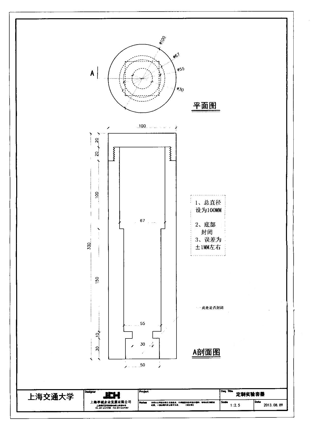
| - | The luminous device is a bridge | + | The luminous device is a bridge connecting electric parts and biological parts. In our project, we chose flasks as our sample container, LEDs as our luminous sources. Since the distribution of light intensity is not evenly in entire space, we must choose a suitable light direction. Side and top were finally abandoned because the walls of flasks can reflect light so that the light intensity is not even in samples. |
| - | After the direction, the distance between bottom and luminous should be decided. | + | After deciding the direction, the distance between bottom and luminous sources should be decided. The distribution of light intensity close to LEDs is not even, in another word, the range of the intensity is fairly broad. However, the intensity will be evenly distributed when a longer distance between light source and the sample. After some basic test, we found that the distribution is mainly even if the distance reaches about 15cm. |
| - | The dark box contains two parts | + | The dark box contains two parts, the upper part holds a flask and the lower part is empty, which make sure that the distance between sample and light source is 15cm. At the bottom of darkbox lies a micro circuit board which contains some electric circuit components and three LEDs: red, green and blue. The LEDs can be controled by MCU(Microprogrammed Control Unit) via lines. |
=LED board= | =LED board= | ||
| - | LED board contains basic circuit components which | + | LED board contains basic circuit components which play the terminal of control system. The board is so tiny and easy to make that is has high expansibility. |
[[image:circuit.jpg|thumb|250px|right|''Fig 2'' circuit diagram of LED board]] | [[image:circuit.jpg|thumb|250px|right|''Fig 2'' circuit diagram of LED board]] | ||
| Line 58: | Line 58: | ||
There are three kinds of circuit components on the board: adjustable resistors, audions and LEDs. | There are three kinds of circuit components on the board: adjustable resistors, audions and LEDs. | ||
| - | Adjustable resistors are used to keep the initial light intensity | + | Adjustable resistors are used to keep the initial light intensity same; audions are used to amplify the signal delivered from MCUs. |
| - | To make boards | + | To make the boards easy to be installed, we put LEDs on one side and other components on the other side. Thus we can fix them at the bottom of dark boxes. |
<br><br><br><br> | <br><br><br><br> | ||
=MCU part= | =MCU part= | ||
| - | MCU part translates the digital value into electronic signal. | + | MCU part translates the digital value into electronic signal. To fulfill this requirement, we built one COM port as input port and 8 PWM(Pulse Width Modulation) output port, each of which can adjust light intensity of one LED, hence one board can control two 3-color LED boards. |
| - | One MCU can not meet our need, because two parallel experiments can show the | + | One MCU can not meet our need, because two parallel experiments can show the differences among three genetic factors. In ideal situation, we need nine 3-color LED boards work at the same time. In other word, we need four MCU boards, and we finally use two as prototype. |
| - | Due to our modular design, the expansibility is fairly | + | Due to our modular design, the expansibility is fairly high. Besides, the LED boards can be changed to 1-color or 2-color boards, and the number of terimals have no limits with enough MCUs. |
Latest revision as of 01:19, 28 September 2013
|
| ||
|
 "
"

