Goals
A Light control system can provide linear light intensity value.
The system can be adjusted in real time.
Software
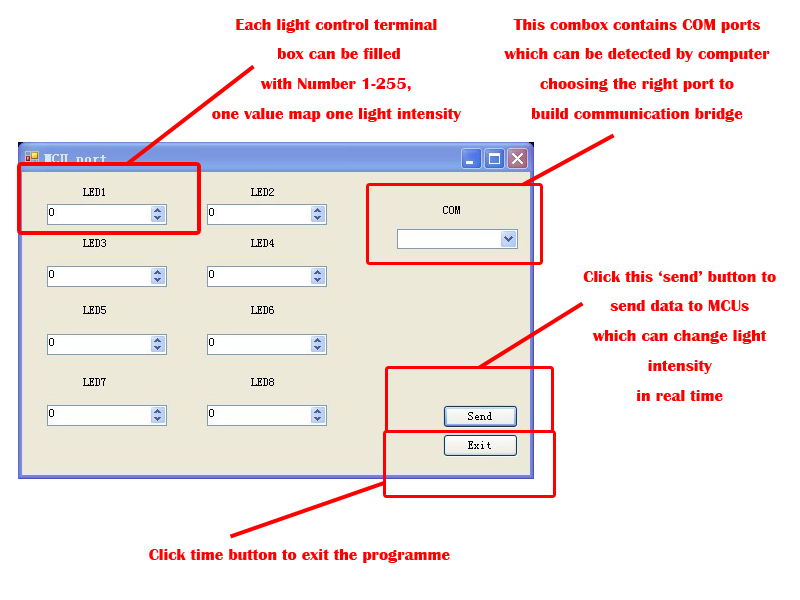
Due to the construction of MCU board, we use COM port as communication bridge. The programme was written by C#. In this progamme, we can adjust the light intensity in real time.
At first, choose one port which is connectting with MCU board from the combobox. Then input the value range 1 to 255 in textboxes and click send bottom. After communication, you can interrupt the connection, and LEDs will keep their light intensity.
Each value sent by computer can generate a PWM wave, and each wave can generate one light intensity.
PWM
Pulse-width modulation (PWM) is a commonly used technique for controlling power to inertial[ambiguous] electrical devices.
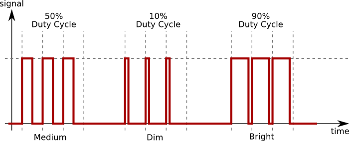
The average value of voltage (and current) fed to the load is controlled by turning the switch between supply and load on and off at a fast pace. The longer the switch is on, compared to the off periods, the higher the power supplied to the load is.
The PWM switching frequency has to be much faster than what would affect the load, which is to say the device that uses the power. Typically switching's have to be done several times a minute in an electric stove, 120 Hz in a lamp dimmer, from few kilohertz (kHz) to tens of kHz for a motor drive and well into the tens or hundreds of kHz in audio amplifiers and computer power supplies.
Period is the time of each pulse, both the On and Off times.
Duty cycle describes the proportion of 'on' time to the regular interval or 'period' of time; a low duty cycle corresponds to low power, because the power is off for most of the time. Duty cycle is expressed in percent, 100% being fully on.
The main advantage of PWM is that power loss in the switching devices is very low. When a switch is off there is practically no current, and when it is on, there is almost no voltage drop across the switch. Power loss, being the product of voltage and current, is thus in both cases close to zero. PWM also works well with digital controls, which, because of their on/off nature, can easily set the needed duty cycle.
PWM signal consists of two parts:
Period
Time of each pulse.
5Hz signal has periods of 1/5 second = 0.2 second.
Duty cycle
The percentage of period the PWM signal is On or high.
A period of 0.2 second and 10%
duty cycle = 0.10 * 0.2 second = 0.02 seconds.
If the signal has a low voltage of 0 and a high voltage of 10 volts, a 50% duty cycle produces an average of 5 volts, a 10% duty cycle produces an average of 1 volt.
LED under PWM control

Output
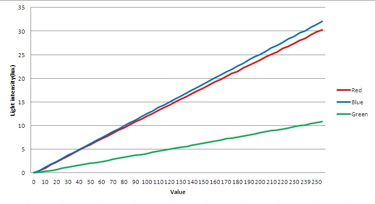
Each light can generate a linear curve of light intensity. Each luminous source focus on one light sensor. Through circles or simulation data, we can probably find a optimal metabolic pathway. With this accurate method, we can precisely explore the expression of each gene in the metabolic system or control traget gene. Further more, this system can also be used in testing creatures' sensibility on light.
 Fig.2 Linear relationship between value and light intensity |
 "
"


